6 Validate and Calculate tools
A mouse click on the Validate and calculate tab activates the validation of the structural model and provides access to the commands that run the optimization and the analysis of the model.
6.1 Validate
In the Validate and calculate tab the software performs the validation of the model according to the calculation model hypotesis and according to engeneering criteria. The structural elements that cannot be validated and that require some modification are displayed in red. The following paragraphs describe the most common cases of not validated elements.
6.1.1 The element does not have a cover
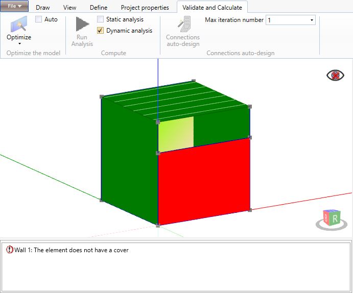
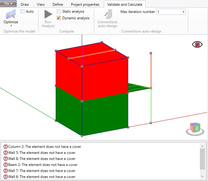
A primary wall must always be connected on its top edge to a floor/roof element.
A beam element must always be connected to a validated floor/roof element or to a validated primary wall.
A column element must always be connected on its top edge to a validated beam element.
6.1.2 Beam not properly supported
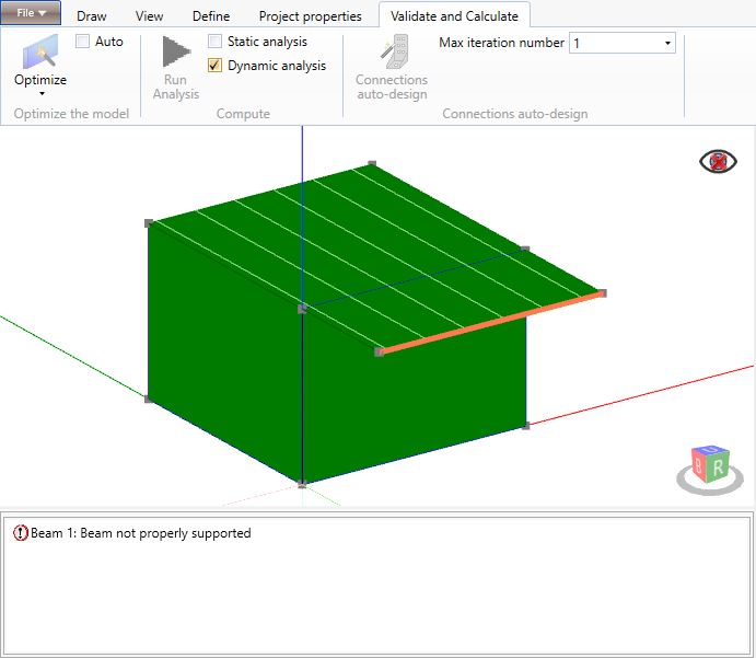
A beam element must always be supported by column and/or wall and/or other beam elements. A floor/roof element cannot support a beam element.
6.1.3 The beam intersects another beam of the same hierarchy
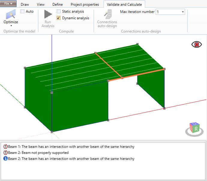
Two beam elements that belong to the same hierarchy must not intersect each other.
When a beam element supports another beam element, the latter must be assigned to a lower hierarchy level. For instance, if the supporting beam is assigned to a primary hierarchy level, the supported beam must be assigned to a secondary level.
6.1.4 Column not properly supported
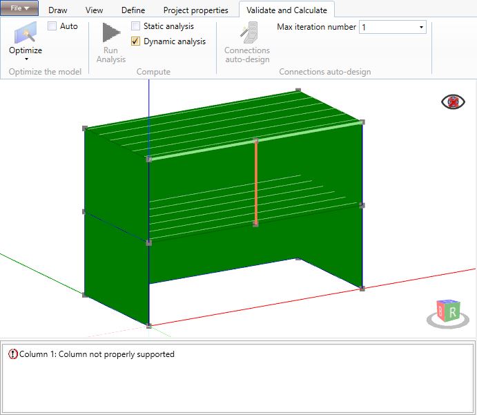
A column element must always be supported by another pillar, by a wall or by a beam element.
6.1.5 Floor not properly supported by beams and walls
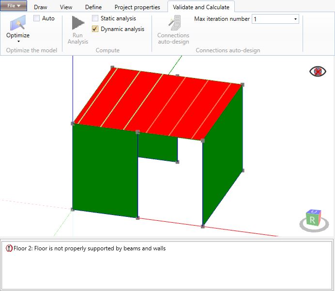
All the joists/calculation lines of a floor/roof element must be properly supported by beam or wall elements.
In the figure above, the 3 calculation lines in red are not supported while the 3 lines in green are well supported.
6.1.6 Floor not well constrained
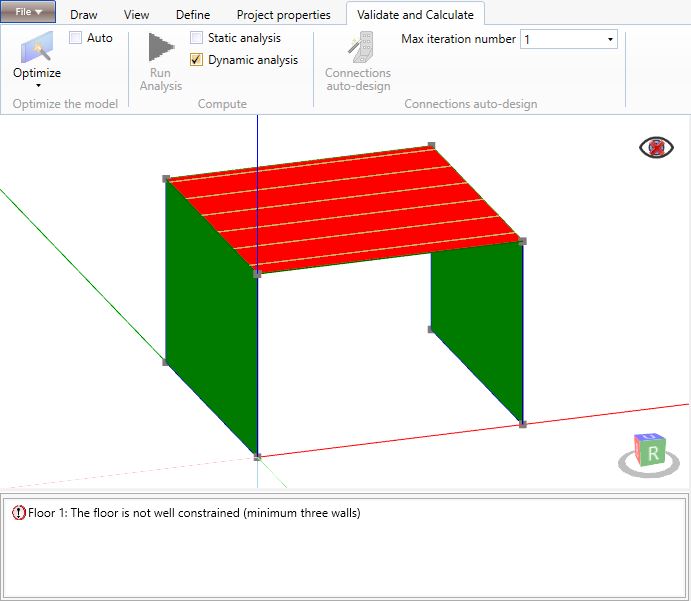
A floor/roof diaphragm must always be supported by at least three well arranged walls in order to constrain it against horizontal actions. These wall elements must be defined as primary elements that are able to withstand horizontal actions.
If a floor/roof diaphragm seems to be well constrained but the software reports the error, the user must verify:
-
if the walls are defined as primary elements;
-
if the software, in the optimization phase, automatically downgrades some wall to a secondary element;
-
if the walls (at least three) are well arranged in the space.
6.1.7 Primary wall supported by more than one element
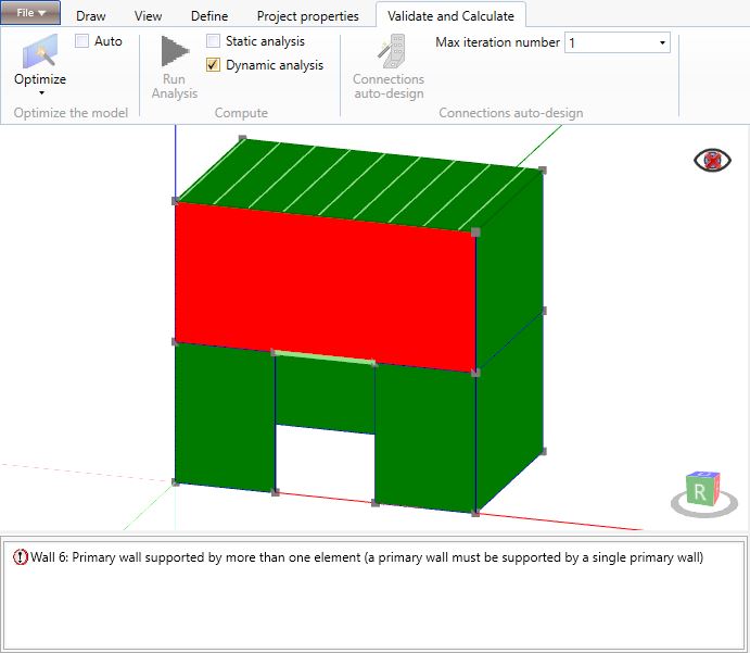
A primary wall element must be supported by one single primary wall for its whole length.
In the figure above, the user has to split the red wall in 3 shorter walls in order to obtain two structurally continuous vertical elements at each side of the opening that, starting from the foundation level, extend up to the roof.
6.1.8 The element supports floors belonging to different levels
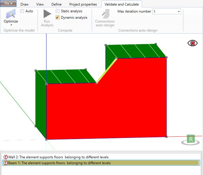
A primary wall element can be connected, on its top edge, only to floor elements belonging to the same diaphragm constraint.
Likewise, the ends of a beam element can be directly or indirectly (through a connection at mid-height of a wall) connected only to floor elements belonging to the same diaphragm constraint.
In the figure above, the user may, if statically acceptable, assign both floors to the same diaphragm constraint or he has to split the wall into 2 shorter walls each one conected to a single floor.
6.1.9 The floor must have a quote greater than 0 and all the base levels
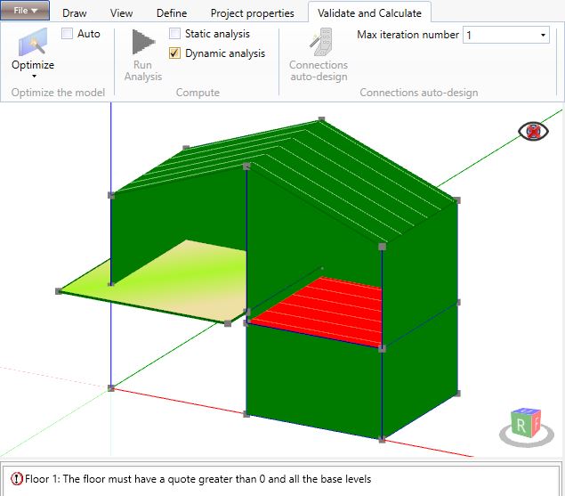
All the floor and roof elements in a model must have a z coordinate greater than 0,00 m and greater than the minimum elevation of the foundation element, if any, where seimic action is applied.
6.2 Optimize and Optimize permanently
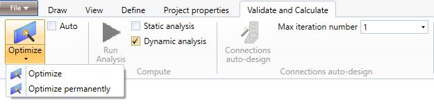
The Validate and calculate tab, once the red alerts are solved, identifies those walls that require some modifications that the software is able to perform automatically before running the analysis.
The Optimize command performs these modifications while the Optimize permanently command performs and permanently saves these modifications.
The walls that require optimization are displayed in orange.
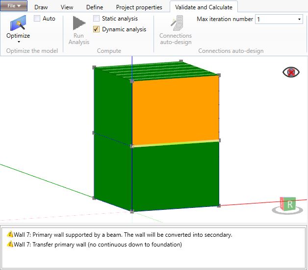
6.2.1 Transfer primary wall (no continuous down to foundation)
The structural elements that withstand the horizontal actions (primary walls) must be continuous down to the foundation level. Therefore, the walls that do not bear on another primary wall must be defined as non-primary elements that are not able to withstand horizontal actions.
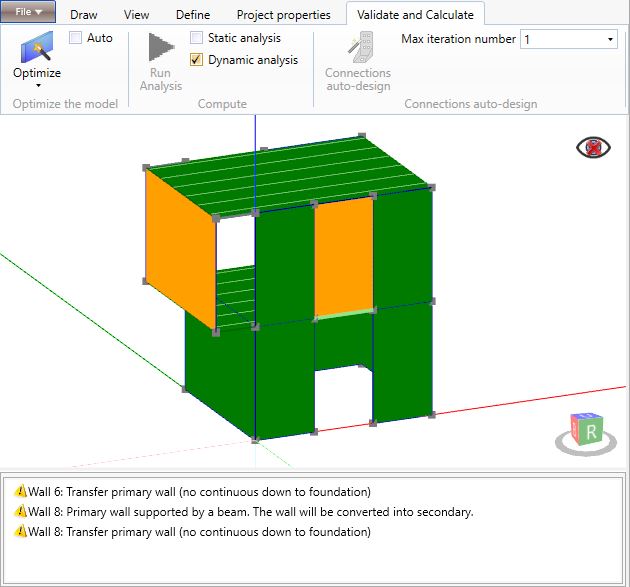
All the primary walls not continuous down to the foundation that directly bear on floors, on beams or on other non-primary walls are displayed in orange.
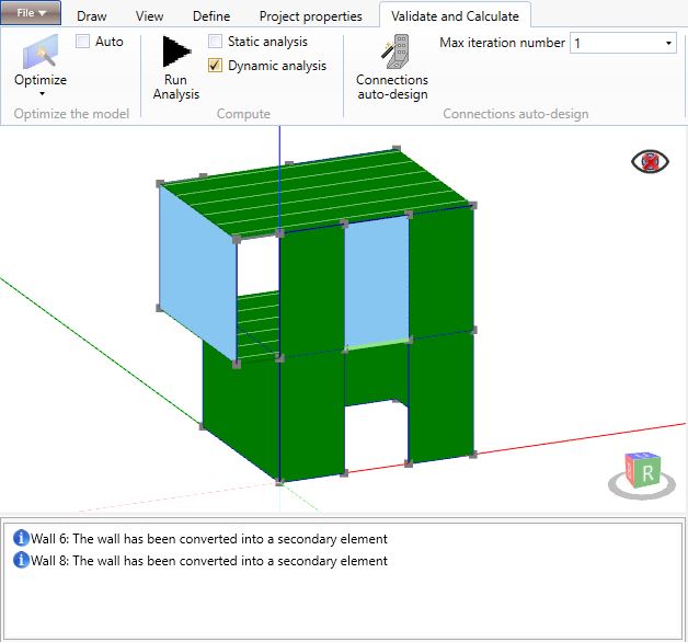
The Optimize command automatically downgrades these walls to non-primary elements.
6.2.2 Short primary wall
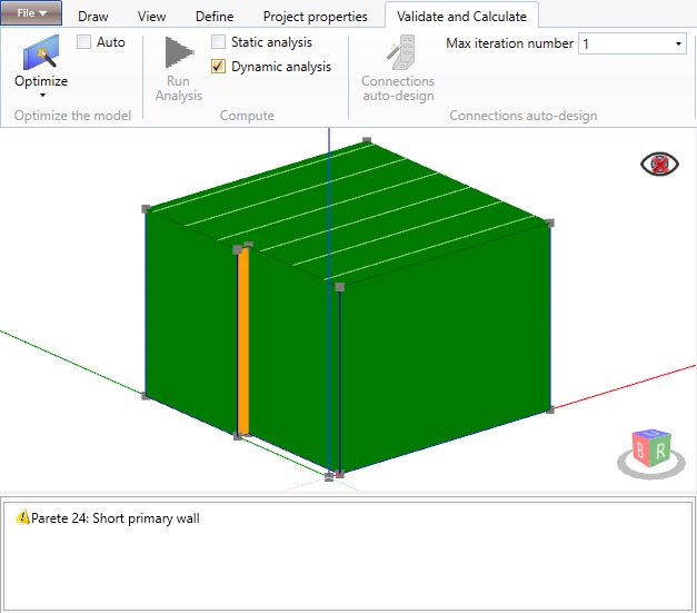
The walls shorter than 0.5 m cannot be considered as primary walls.
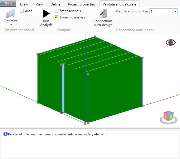
The Optimize command automatically downgrades these walls to non-primary elements.
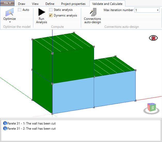
6.2.3 The wall must be cut
When, in a structural system of primary walls one on top of each other, one of them extends beyond the end of the one above it by a length equal to or greater than the 45% of its length (and not more than 6 m for CLT walls and 1 m for framed walls), it has to be split into two walls.
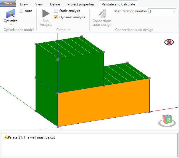
The Optimize command automatically splits the wall at the lower level into two elements.
6.2.4 The primary wall is supported by a beam
A primary wall supported by a beam element, even if the beam is directly supported by another primary wall, cannot be defined as a primary wall and the software will downgrade it to a non-primary element.
6.3 Run analysis
The Run Analysis command allows to run the structural analysis of the model. The model can be correctly analysed when all the elements are green or blue.
The user can choose between different analysis types:
-
Analysis of vertical wind actions;
-
Seismic static analysis*;
-
Seismic dynamic analysis*.
* the software always runs the analysis of vertical and wind actions
6.4 Connections auto-design
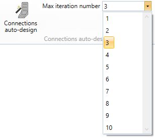
The Connections auto-design command allows to run the dynamic analysis of the model and, at the same time, the auto-design of the connections at the base of each primary wall according to an iterative process.
The software, according to the connection types assigned by the user to each wall, edits the number of tensile connections at each wall end and the spacing between shear connections in order to achieve a demand/capacity ratio as close as possible to 90%. At each iteration, the software recalculates and updates the connections strength and stiffness and runs the analysis.
The user can set the maximum number of iterations. Please, refer to the Settings section in Project properties for further details on Automations settings.