8. Elements properties
If the user selects a model element, on the right side of the screen the property inspector window will appear where information on the geometry, on the mechanical properties and on the loads assigned to the selected element are provided. In the model definition phase, the user can modify the assigned properties through the available drop-down menu. In the analysis stage, the property inspector also provides details on the stresses/forces/displacemente and on the verifications of the selected element.
8.1 Wall
8.1.1 Geometry
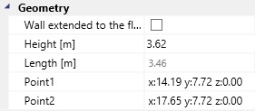
The user can:
-
extend the selected wall up to floor or roof element above it by checking the checkbox;
-
modify the element height;
-
modify the element length.
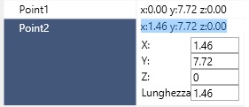
In order to modify the wall length, the user can select and edit the coordinates of one of the end points of the wall (Point 1, Point 2). The user can assign new values to the point coordinates or modify the element length. If the user edits the element length, the software will lengthen or shortens it by modifying the coordinates of the selected end point.
8.1.2 Info
In the Info box the user can:
-
edit the wall typology;
-
edit the assigned loads;
-
edit the assigned connections;
-
edit the service class;
-
choose whether to include or not the element in the calculation report.
The Info box provides the following informations:
8.1.2.1 Framed Wall
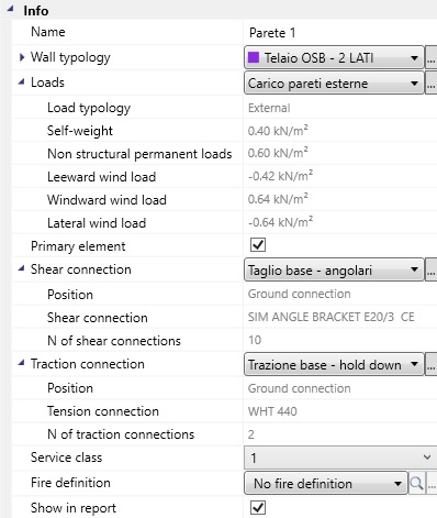
Wall typology
-
Typology: the typology of the wall;
-
Material: the studs and plates material;
-
External stud: cross-section area of the external stud;
-
Internal stud: cross-section area of the internal stud;
-
Sheeting panel side 1: the panel material and type;
-
Sheeting panel side 2: the panel material and type.
Loads
-
Load typology: load applied on internal walls or on external ones;
-
Self-weight load: the self-weight load, per unit area, of the walls;
-
Non structural permanent load: load, per unit area, of the surface finishing;
-
Leeward surface*: wind pressure on the non directly exposed wall;
-
Windward surface*: wind pressure on the directly exposed wall;
-
Primary element: it indicates whether the element is meant to withstand horizontal actions or not.
Connection**
-
Position: connection position (ground connection or upper level connection);
-
Shear connection: shear connection typology;
-
N of shear connection: number of shear connections;
-
Tension connection: tensile connection typology;
-
N of hold-downs/tie-downs: total number of tensile connections;
* only for external walls; ** only in case of primary wall.
8.1.2.2 CLT wall;
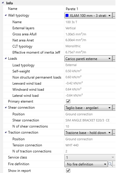
Wall typology
-
Typology: wall typology;
-
Name: cross-section name;
-
External layers: orientation of the external layers;
-
Gross area Afull: gross area of the cross-section;
-
Net area Anet: area of the vertical layers of the cross-section;
-
CLT typology: monolithic or jointed;
-
Effective moment of inertia Jeff: moment of inertia calculated by considering the vertical layers connected through the transversal ones;
Loads
-
Load typology: load applied on internal walls or on external ones;
-
Self-weight load: the self-weight load, per unit area, of the walls;
-
Non structural permanent load: load, per unit area, of the surface finishing;
-
Leeward surface*: wind pressure on the non directly exposed wall;
-
Windward surface*: wind pressure on the directly exposed wall;
-
Primary element: it indicates whether the element is meant to withstand horizontal actions or not.
Connection**
-
Position: connection position (ground connection or upper level connection);
-
Shear connection: shear connection typology;
-
N of shear connection: number of shear connections;
-
Tension connection: tensile connection typology;
-
N of hold-downs/tie-downs: total number of tensile connections;
* only for external walls; ** only in case of primary wall.
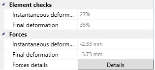
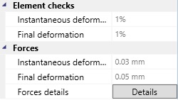
8.1.3 Element checks
The Element checks box provides the following data:
8.1.3.1 Framed wall
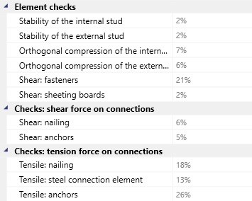
Element checks
-
Instability of the internal stud: check of the stability of the internal stud;
-
Instability of the external stud: check of the stability of the external stud;
-
Orthogonal compression of the internal stud: check of the orthogonal compression under the internal stud;
-
Orthogonal compression of the external stud: check of the orthogonal compression under the external stud;
-
Shear fasteners: check of the connection between the sheeting panels and the frame;
-
Shear panels: check of the sheeting panels in shear.
Check of the shear force on connections:
-
Shear force on angle bracket: check of the shear capacity of the angle bracket;
-
Shear force on anchors: check of the shear capacity of the anchors;
-
Nailed connection: check of the nailing in case of punched plates;
-
Steel plate shear failure: check of the punched plate shear failure.
Checks of the tension connection:
-
Nailing: check of the nailed connection resistance;
-
Failure of the net cross-section: check of the hold-down tensile strength (steel ultimate tensile strength);
-
Anchors tension failure: check of the anchors tensile failure;
-
Yielding of the gross-section: check of the steel plastic resistance (gross cross-section of the plate);
-
Tension failure of the net cross-section: check of the ultimate tension resistance of the plate net cross-section.
8.1.3.2 CLT wall
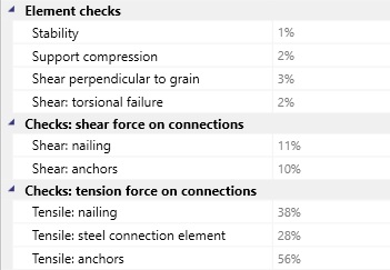
Element checks
-
Instability: check of the element stability;
-
Support compression: check of the support compression;
-
Shear perpendicular to grain: check of shear bearing in the boards ;
-
Torsional failure: check the shear failure due to torsion-like mechanism in the gluing interfaces.
Check of the shear force on connections:
-
Shear force on angle bracket: check of the shear capacity of the angle bracket;
-
Shear force on anchors: check of the shear capacity of the anchors;
-
Nailed connection: check of the nailing in case of punched plates;
-
Steel plate shear failure: check of the punched plate shear failure.
Checks of the tension connection:
-
Nailing: check of the nailed connection resistance;
-
Failure of the net cross-section: check of the hold-down tensile strength (steel ultimate tensile strength);
-
Anchors tension failure: check of the anchors tensile failure;
-
Yielding of the gross-section: check of the steel plastic resistance (gross cross-section of the plate);
-
Tension failure of the net cross-section: check of the ultimate tension resistance of the plate net cross-section.
8.1.4 Forces
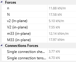
The forces meaning is better explaind in the part 7: Analysis tools.
8.1.5 Displacement
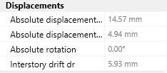
The data provided in the Displacement box include the absolute displacements on the top of the walls and the elastic inter storey drift (in the direction on the length of the wall).
8.2 Column
8.2.1 Geometry/Info
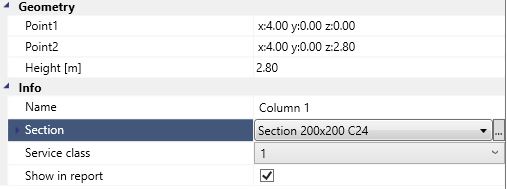
In the Geometry box the user can edit the position and the height of the selected column. In the Info dialog box the user can modify the cross-section properties. The following informations are provided:
-
Name: name of the element;
-
Service class: the service class depending on the timber humidity;
-
The choiche whether to include or not the element in the calculation report.
8.2.2 Checks/forces
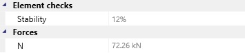
The Element checks and Forces dialog box provides the checks of column stability and the values of the axial force.
8.3 Floor (Roof)
8.3.1 Info
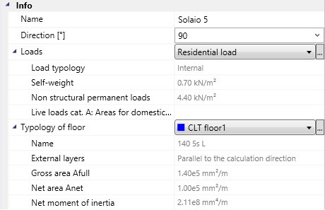
In the Info dialog box the user can modify:
-
the floor direction;
-
the applied loads;
-
the floor typology;
-
the service class;
-
the deformation limits;
-
the details for the vibration checks;
-
the choiche whether to include or not the element in the calculation report.
The box provides also the following informations:
Info
- Name: name of the element;
Loads
-
Load typology (internal or external load);
-
Self weight of the floor;
-
Non structural permanent load of the floor;
-
Live loads category.
Typology of floor
-
External layers*: orientation of the panel external layers (parallel or orthogonal to the calculation direction);
-
Area A: area of the cross-section;
-
Gross area Afull: gross area of the cross-section;
-
Net area Anet: area of the layers parallel to the calculation direction;
-
Moment of Inertia Jz**;
-
Moment of Inertia Jy***:
-
Net moment of Inertia Jnet*: moment of inertia of the layers parallel to the calculation direction.
* only in the case of CLT floor; ** only in the case of joist floor; *** only in case of joist or solid wood floor.
8.3.2 Checks/Forces
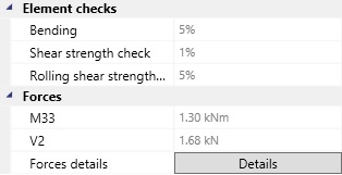
The meaning of the data in the Checks and Forces boxes do not need to be explained. The only term that changes, according to the floor type, is the shear one: in case of CLT floor the software checks both the shear strength and the rolling shear strength.
8.3.3 Details (Solid Wood Floor/Joists Floor)
If the user selects the Details command a window will appear where the static schemes and the enveloped diagrams of forces (or deformations) are displayed.
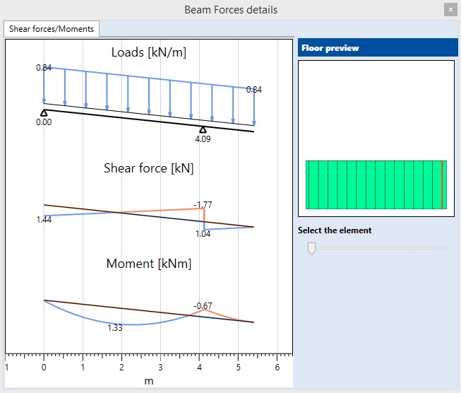
The user can select the element whose diagram is desired to be displayed by moving the pointer in the floor preview.
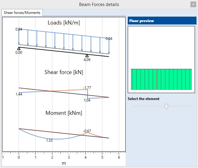
NB: If no values are displayed, it means that they are lower than 0.01 units.
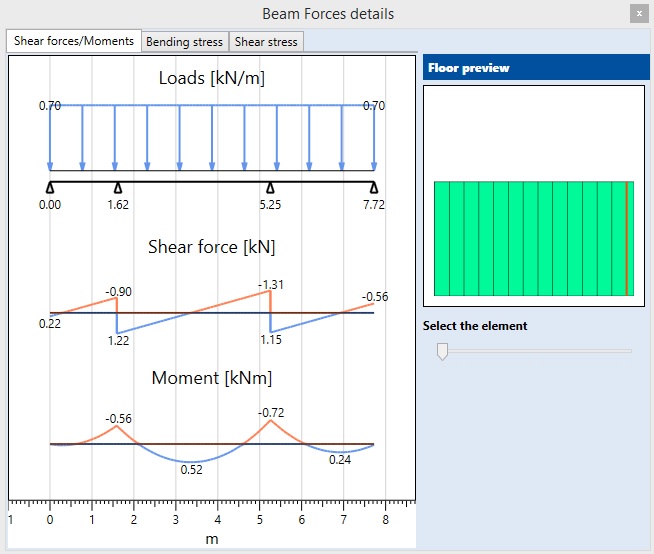
8.3.3 Details (CLT Floor)
If the user selects the Details command a window with the following data will be displayed:
-
Enveloped diagrams of forces (or deformations)
-
The bending stresses
-
The shear stresses
NB: If no values are displayed, it means that they are lower than 0.01 units.
8.4 Beam
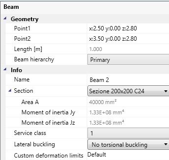
8.4.1 Geometry/Info
In the Info box the user can edit the following parameters:
-
the beam length (as for the wall elements);
-
the cross-section typology;
-
the beam hierarchy (Primary element, 2nd, 3rd);
The box also provides the following information:
-
Name: the element name;
-
Service class: according to the timber moisture;
-
Lateral buckling restraints;
-
Deflection limits;
-
Choiche whether to include the element in the calculation report or not.
8.4.2 Checks/Forces
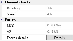
The meaning of the data do not need to be explained.
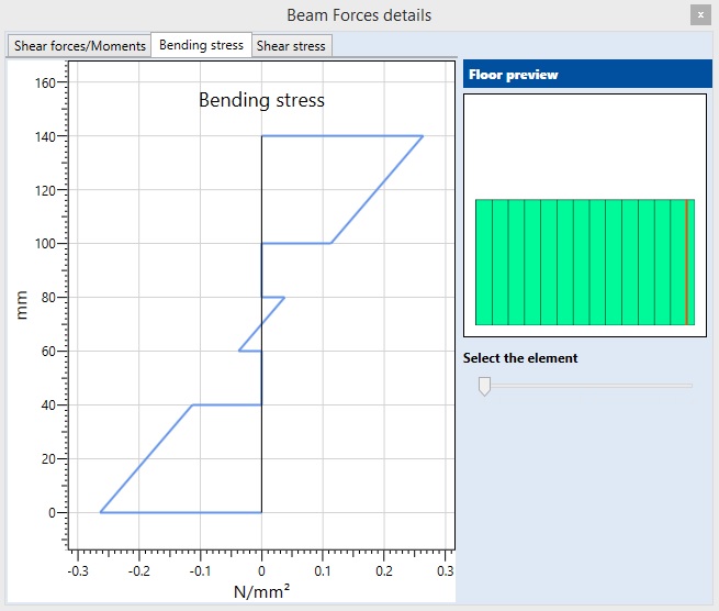
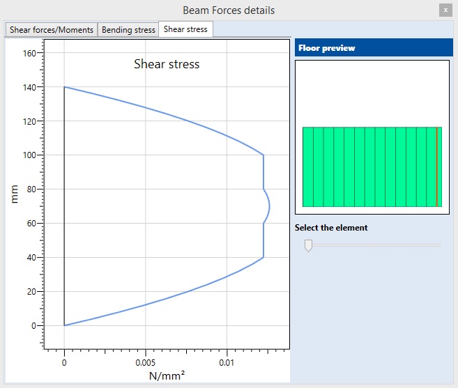
8.4.3 Details
If the user selects the Details command, a window reporting the static schemes and the enveloped diagrams of forces (or deformations) will appear.
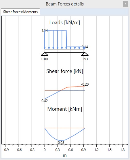
NB: If no values are displayed, it means that they are lower than 0.01 units.
8.5 Line and Grid
8.5.1 Line
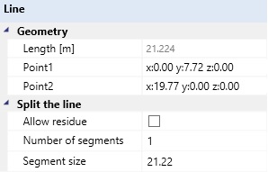
The user can:
-
edit the length and the position by changing the coordinates of the end points (see 8.1.1 Wall Geometry).
-
choose the number of segments according to which divide the line;
-
choose the segments length according to which divide the line.
The Allow residue option, if the line length is not a multiple of the specified segments length, will create a last segment whose length is equal to the residue of the line length/segment length ratio.
8.5.2 Grid
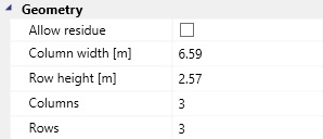
The user can:
-
define the number of columns and rows of the grid;
-
define the column width and the row height.
IAs for the line definition (see 8.5.1), the user can select the Allow residue option.