2 Tools of Draw menu
The commands in the Draw menu allow the user to draw the structural model. Other useful informations can be found in Chapter 8.

2.1 Dynamic input
The drawing of the Structural elements, the insertion of the Guides and the use of the Edit selection commands can be carried out using the Dynamic input functions. To use this function, after defining the first point, enter the length of the element, press the Tab key and define the angle (polar coordinates) or the coordinates separated by commas (Cartesian coordinates).

To switch from relative coordinates to absolute coordinates, just type #.
2.2 Structural elements
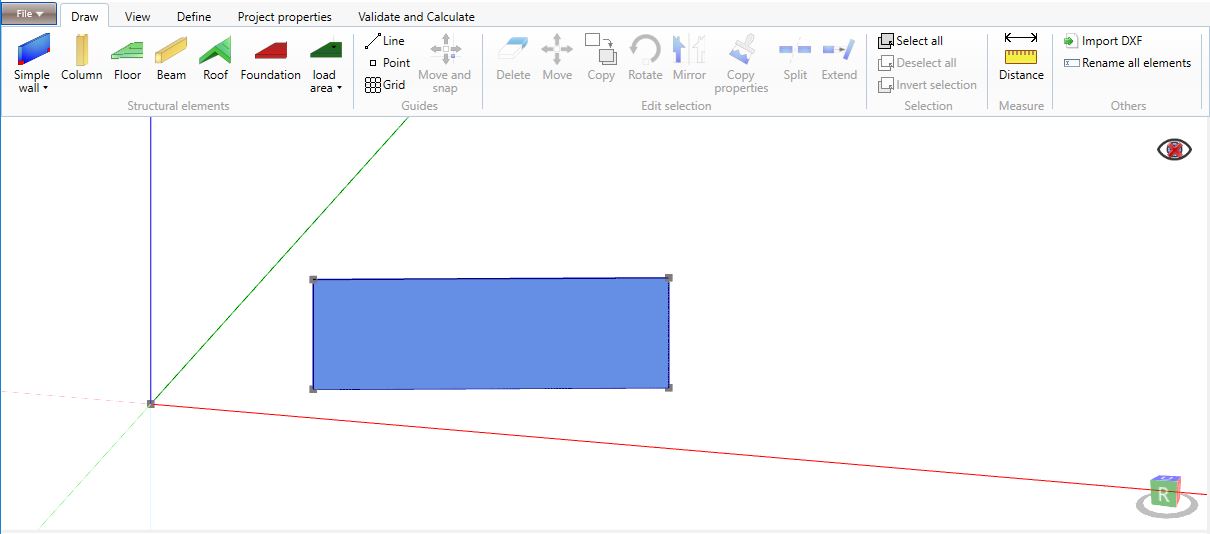
2.2.1 Simple wall

The Simple wall element can be drawn by selecting two points on the screen. The software automatically assigns to the wall an height equal to 2.80 m; the user can modify it later (see Chapter 8).

The wall element can also be defined typing Wall in the command line and thereafter the points coordinates. The first point is defined by the absolute coordinates, i.e. referring to the global system (for instance: 4,4,0). The second point coordinates can be defined by using either the absolute or the relative coordinates. If the user prefers the second way, he must type the symbol @ before the coordinates (for instance: @4,4,0 where the values represent the distances along the three directions x, y and z).
2.2.1 Polygonal wall

The Polygonal wall element can be defined by drawing the wall vertexes on the screen. This command is used to define non rectangular walls or walls supporting a beam on their upper vertex like the ridge ones.

The Polygonal wall command can also be exploited to define the nodes where a beam element connects to a wall along its vertical edge. The user should indicate, in addition to the wall vertexes, the connection point between the wall and the beam element.


2.2.2 Column
The Column element can be defined by a single point on the screen: the software assigns automatically to it an height equal to 2.80 m.
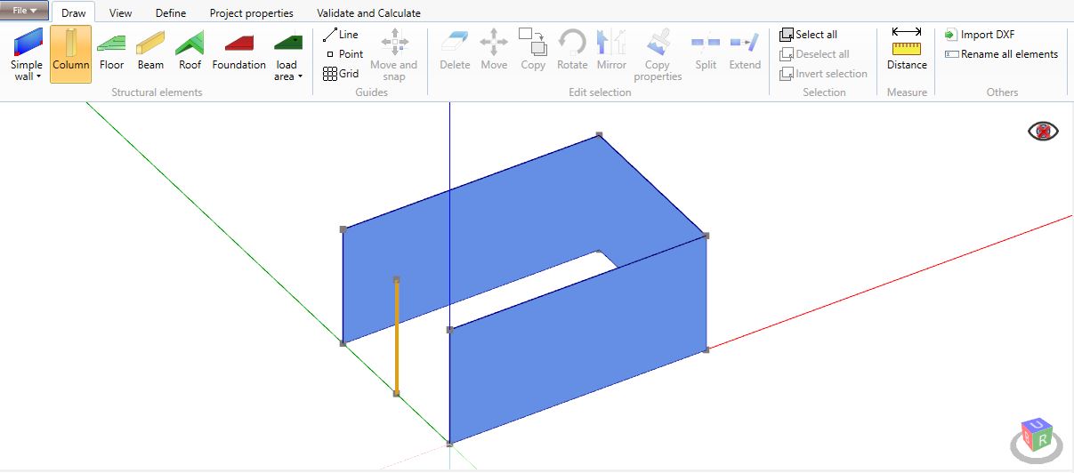
The user can use the command line to create a new element by typing Pillar and then the first point coordinates.
2.2.3 Floor element

The Floor element can be straight designed on the screen by defining at least three points. The points must be coplanar, with the same z-coordinate and belonging to the vertexes of an any form polygon.
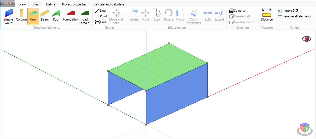
The user can create the Floor element directly from the command line by typing Floor and then the points coordinates.
2.2.4 Beam element
The Beam element can be drawn on the screen by selecting the two end points.
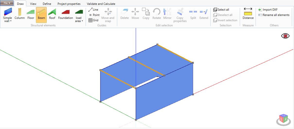
The user can define the Beam element directly in the command line by typing Beam and then inputting the points coordinates.
2.2.5 Roof element
The Roof element is defined in the same way as for the Floor element (see Floor element). The Roof command provides the input of a pitched roof with a grade to the horizontal at no higher than 80 degree.
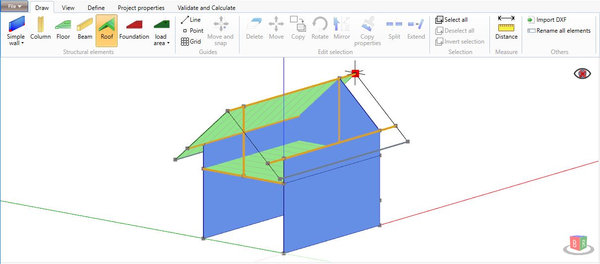
As for the other elements, the Roof can be defined by typing Roof and inputting the points coordinates in the command line.
2.2.6 Base element
The Base element can be straight designed on the screen by defining at least three points. The points must be coplanar, with the same z-coordinate and belonging to the vertexes of an any form polygon. The Base element is very useful when there are buildings with sections starting from different levels.
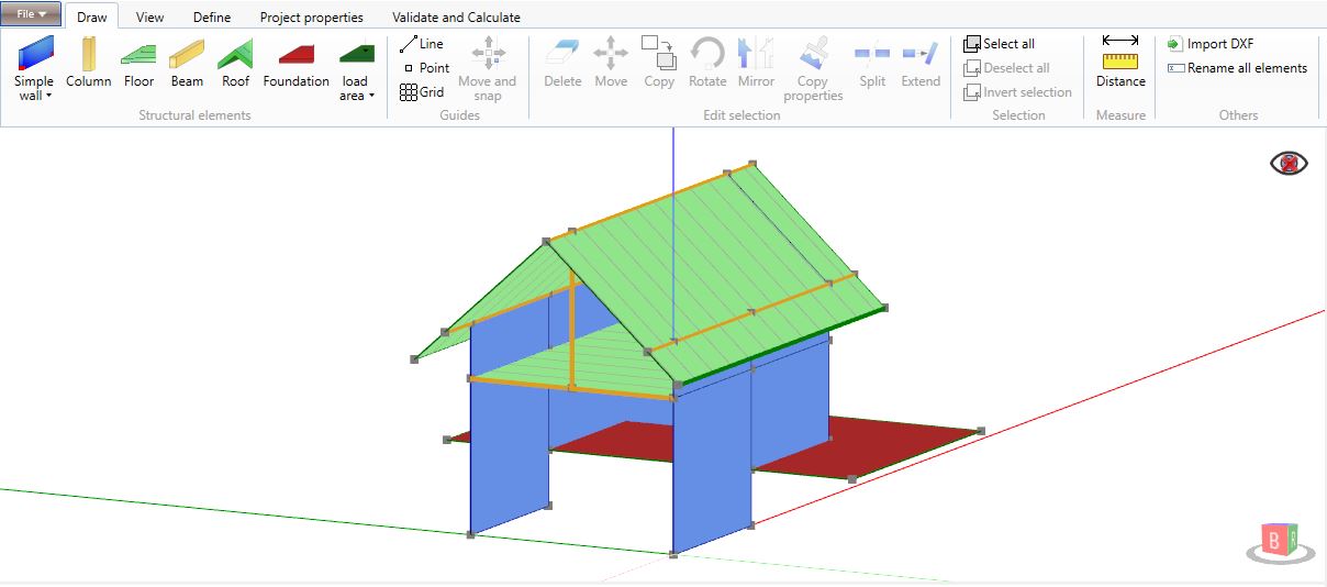
The user can define the Base element directly in the command window by typing Base and then the points coordinates.
2.2.7 Load area
The Load area element can be straight designed on the screen by defining at least three points on a floor element or on a roof one. The points must belong to the vertexes of an any form polygon. The assigned load to the load area replaces the one assigned to the uderlying floor or roof. The Load area element is very useful in the case of not uniform loads.
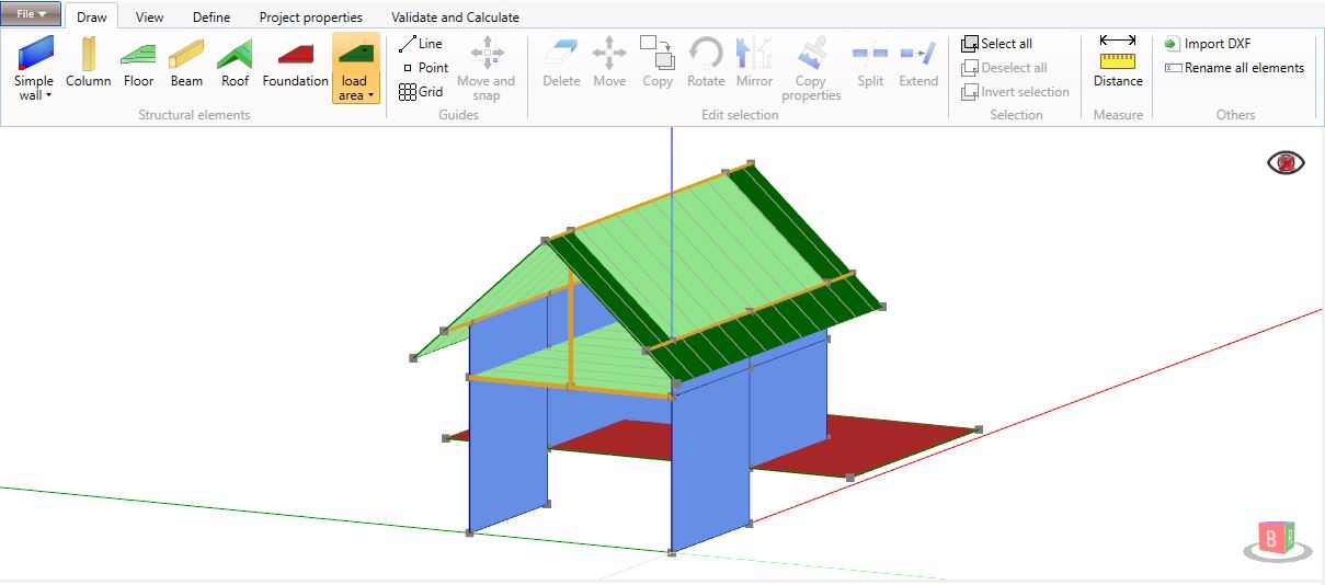
The user can define the Load area element directly in the command line by typing Load and then the points coordinates.
2.2.8 Linear load (LinearLoad)
The Linear load can be drawn on the screen by selecting the two end points on a floor or on a roof.

The user can define the Linear load element directly in the command line by typing LinearLoad and then the points coordinates.
2.3 Guides
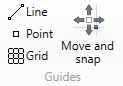
2.3.1 Line

The Line command is used to drawn a line in any direction. Thanks to the lines, the user can easily draw the structural elements in the model. The line can be defined by selecting two point on the screen or typing Line in the command line and then inputting the points coordinates.
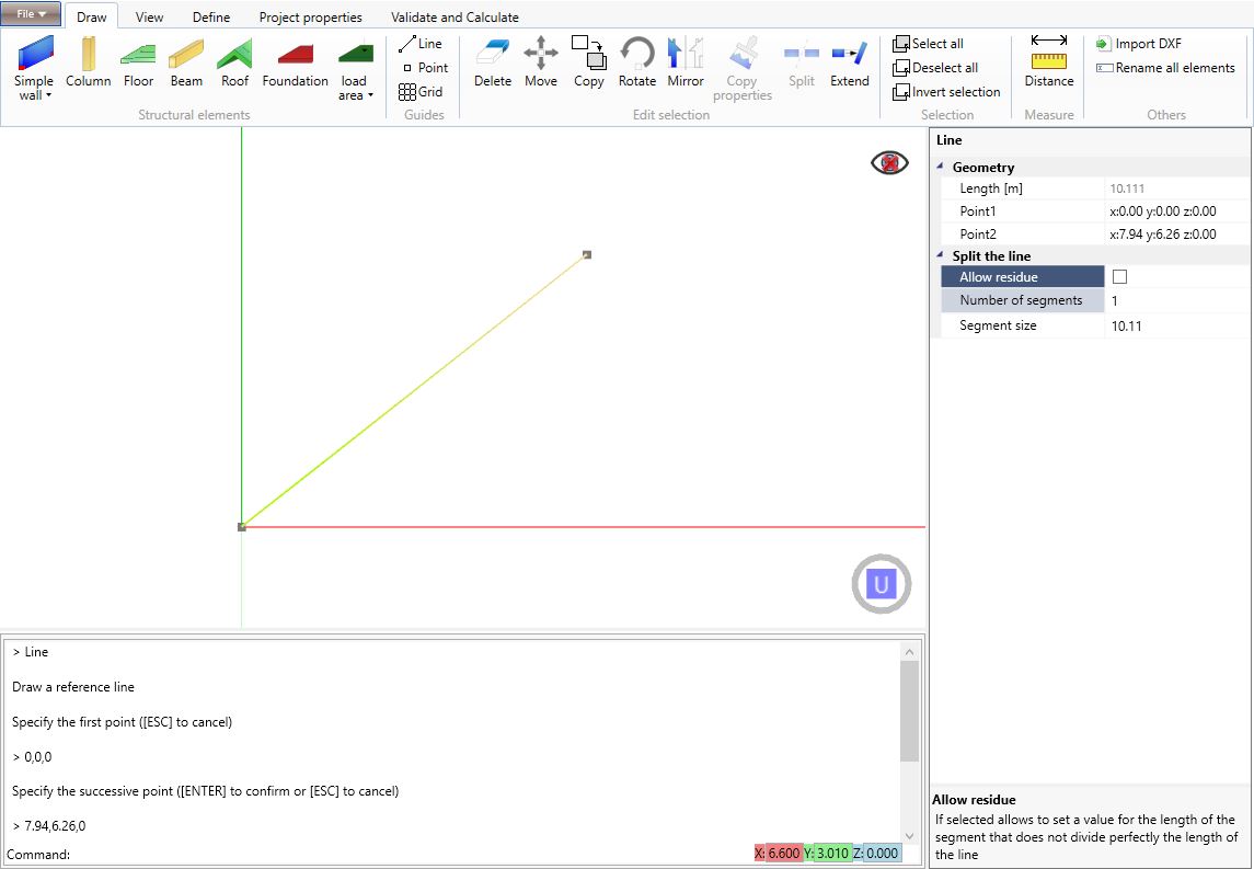
The Line element, once selected, can be edited by acting on the Property inspector on the right side of the software window. The user can modify the position of the end nodes and divide the line in segments according to a user-defined size or according to the desired number of segments.
2.3.2 Point

The command is used to directly draw on the screen a point that can be useful for the drawing process. The point can also be defined by typing Point in the command line and then inputting the point coordinates.
2.3.3 Grid

The Grid command defines, in the x-y plane, a grid of equidistant points belonging to perpendicular directrices. The user can select two points on the screen or type Grid in the command line and the points coordinates.
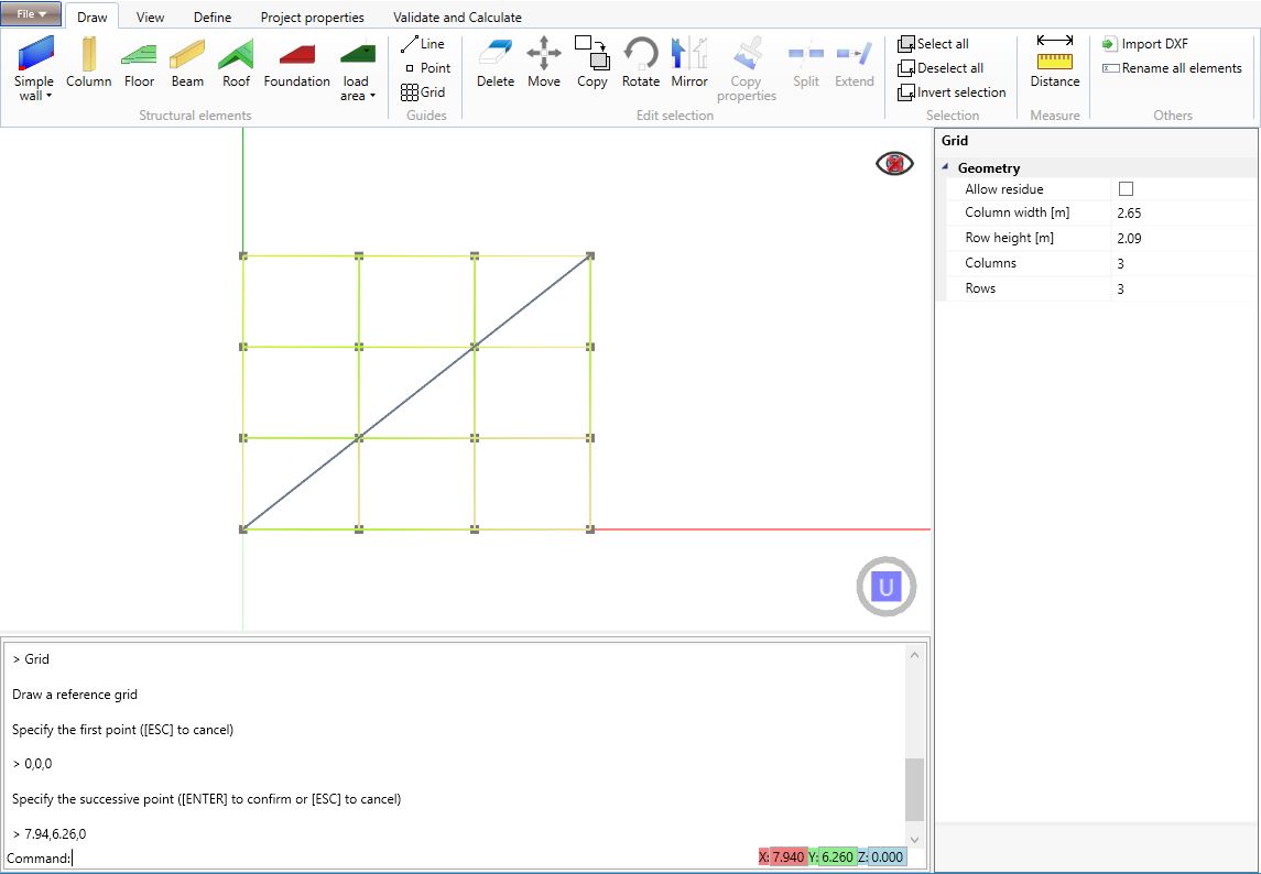
The Grid element, once selected, can be edited by acting on the Property inspector on the right side of the software window. The user can modify the number and the dimension of rows and columns.
2.3.4 Move and snap (MoveAndSnap)

The Move and snap command is exploitable on point and/or line elements and allows the user to move these elements and adapt them to the pre-existing elements in the model. The user may, optionally and in the command line, specify the threshold to the distance of the snap. This feature is useful when the user wants to import the drawings of the plans of each level of the structure and adapt them to the already modelled elements.
2.4 Edit selection
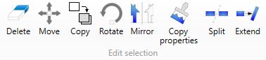
2.4.1 Delete

The Delete command deletes all the selected elements. The user can type Delete on the command window or press Del on the keyboard.
2.4.2 Move

The command moves in the model all the selected elements. To move the elements the user has to input the initial and the final points directly on the screen or typing their coordinates in the command line. As for the other commands, the user can also type Move in the commands line.
2.4.3 Copy

This command is used to copy the selected graphical elements. The user has to input the initial and the final points that define the offset directly on the screen or inputting the coordinates in the command line. The user can also type Copy in the command line.
2.4.4 Rotate (Rotate)

The Rotate command allows to rotate the selected elements about a vertical axis whose location is user-defined and according to an angle user-defined as well. The user has first to select a point for the rotation axis and then two points that define the rotation angle. As for the other commands, the user can also select one or more elements, type Rotate in the command line and then input the rotation point coordinates and the rotation angle or two points coordinates that can define it.
2.4.5 Mirror (Mirror)

The Mirror command allows to copy and mirror the selected elements about a vertical plane whose direction in the x-y plane is user-defined by selecting two points belonging to that plane. As for the other commands, the user can also select one or more elements, type Mirror in the command line and then input two points coordinates that define the mirroring plane.
2.4.6 Copy properties (copyProperties)

The Copy properties command allows to copy the properties of the selected elements on one or more elements of the same type. The user has simply to select these last elements and press Enter. As for the other commands, the user can also select one or more elements, type copyProperties in the command line and then select the target elements and press Enter.
2.4.7 Split (Split)

The Split command allows to split the selected elements at the intersection with other elements. The user has simply to select these last elements and press Enter. As for the other commands, the user can also select one or more elements, type Split in the command line and then select the target elements and press Enter.
2.4.8 Extend (Extend)

The Extend command allows to extend the selected elements towards other elements. The user has simply to select these last elements and press Enter. As for the other commands, the user can also select one or more elements, type Extend in the command line and then select the target elements and press Enter.
2.5 Selection
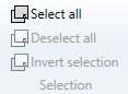
2.5.1 Select all
The command Select all is used to select all the graphical elements of the model. The user can use directly the command line typing Select All in it.
2.5.2 Deselect all
The command deselects all the selected graphical elements. The user can use directly the command line typing Select None in it.
2.5.3 Invert selection
The command is used to invert the selection. The command can be activated by typing Select Invert in the command line.
Note: the user can select the objects left-clicking the mouse. By moving the pointer from the left to the right, all the objects that entirely lie within the rectangular selection will be selected; by moving the pointer from the right to the left all the objects that entirely lie within the rectangular selection and those which cross the selection border will be selected.
2.6 Distance
2.6.1 Distance (Distance)

The Distance command measures the distance between two selected points. The measurement data along the axis (x, y and z) are displayed on the command line (for instance: Distance: 4,53 m; X: 3,21 m; Y: 7,10 m; Z: 0,86 m;). The command can be activated by typing Distance in the command line.
2.7 Others
2.7.1 Import Dxf

The command allows the user to import a dxf file within points, lines and polylines, useful to define, for instance, a pitched roof.
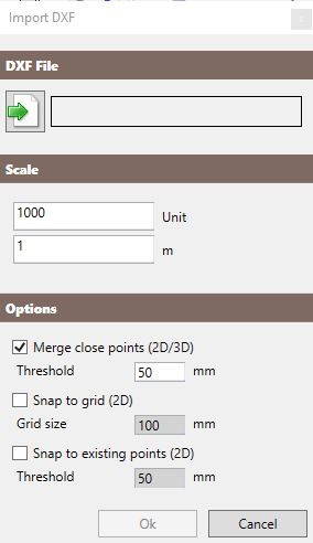
The command is linked to a window in which the user can select the dfx file, specify the importing scale and set some import options.
If the scale is too much small, the software will alert the user.
The user may activate the following import options:
-
Merge close points (2D/3D): option available for the import of both 2D and 3D drawings that allows to merge those points (even belonging to lines) whose mutual distance is lower than the user-defined threshold. The software is also able to find the intersection between two lines and merge their point there.
-
Snap to grid (2D): option available for the import of 2D drawings (in the x-y plane) that allows to adapt the imported lines and points to a grid whose dimension is user-defined.
-
Snap to existing points (2D): option available for the import of 2D drawings (in the x-y plane) that allows to adapt the imported lines and points to the pre-existing elements of the model by taking as reference their nodes. The user can set the maximum snap threshold.
Notes: these options may be very useful for the optimisation of a dxf drawing import. The user should pay attention to the import options since wrong settings may generate some misalignments.
2.7.2 Rename all elements
The command allows to rename and rearrange all the elements in the model according to the currently set language and in ascending numeric order.