3 Tools of the View Menu
The View tools help the user to display the structural model.
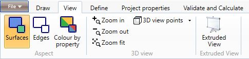
3.1 Aspect
3.1.1 Surfaces

The Surfaces command allows the user to display the surfaces and the definition points of the structural elements.
3.1.2 Edges

The Edges command allows the user to display the edges of the structural elements.
3.1.3

The command allows the user to display the elements properties: walls, floors, roofs, columns, beams. The user can easily display the materials, the cross-sections, the types, the connections properties, the loads and other properties.
3.2 3D View
3.2.1 Zoom in

The command allows the user to zoom in the current view.
3.2.2 Zoom out

The command allows the user to zoom out the current view.
3.2.3 Zoom fit;

The command allows the user to display all the graphical elements in the current view.
3.3 3D Point of view
The menu allows to choose a type of view (orthogonal or axonometric) to display the current view.
3.3.1 Up

The command sets a view from above.
3.3.2 Down

The command sets a view from below.
3.3.3 Left

The command sets a view from the left.
3.3.4 Right

The command sets a view from the right.
3.3.5 Front

The command sets a frontal view.
3.3.6 Back

The command sets a back view.
3.3.7 SW

The command sets an axonometric view: South-West.
3.3.8 SE

The command sets an axonometric view: South-East.
3.3.9 NW

The command sets an axonometric view: North-West.
3.3.9 NE

The command sets an axonometric view: South-East.
Note:
The user can perform zoom and pan with a wheel mouse:
-
zoom: scrolls up and down to zoom out and zoom in the view;
-
pan: press the mouse wheel button and drag the mouse;
-
point of view: rigth-click the mouse and drag it.
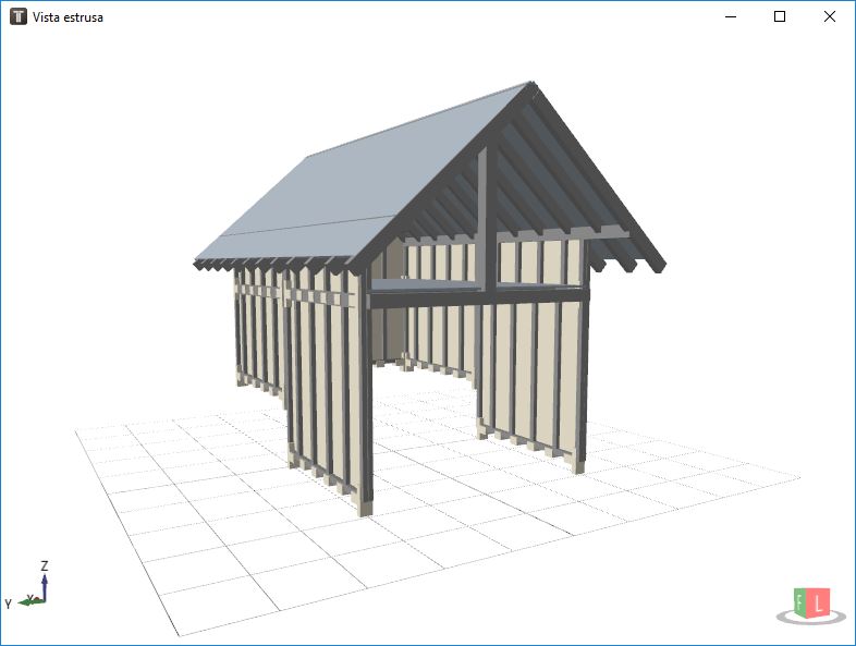
3.4 Extruded view
3.4.1 Extruded view

The command opens a window where the 3D extruded model is displayed. This view allows the user to inspect in detail the geometric properties assigned to the structural elements and to find potential mistakes. The extruded model can also be exported in .ifc format in the Export section of the software.
3.5 Other tools
3.5.1 Select view

If the user selects the eye icon on the upper right side of the screen a checkbox will appear. The user can select the elements or the levels he wants to display.
The non displayed elements can not be selected.
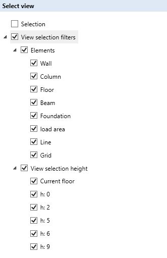
If the user select Current floor a cursor will appear (on the lower right side of the console) that allows to choose the level to display.
3.5.2 Point of view

The icon, in the lower right side of the visualization window, allows the user to set the orthogonal views (see: 3D Point of view) by clicking on the desired cube face.