4 Tools in the Define menu
The tools in the Define menu allow the user to:
-
consult the materials and joints archives;
-
define the structural elements typologies;
-
define the loads on the structural elements.
4.1 Materials archive
4.1.1 Timber

The Timber command allows to consult the performance data of:
4.4.1.1 Homogenous and combined glulam:
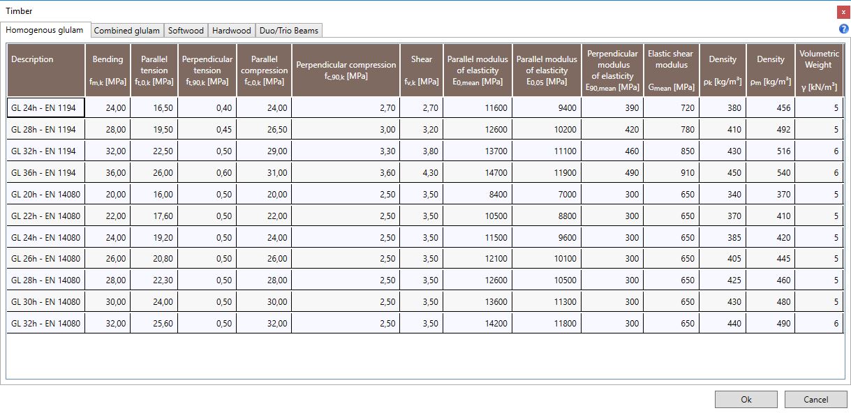
The tables provide the mechanical properties values of different strength classes:
-
fm,k: bending strength;
-
ft,0,k: parallel tension strength;
-
ft,90,k: perpendicular tension strength;
-
fc,0,k: parallel compression strength;
-
fc,90,k: perpendicular compression strength;
-
fv,k: shear strength;
-
E0,mean: mean value of the parallel modulus of elasticity;
-
E0,05: characteristic value of parallel modulus of elasticity;
-
E90,mean: mean value of the perpendicular modulus of elasticity;
-
G,mean: mean value of the elastic shear modulus;
-
ρ,k: density (characteristic value);
-
ρ,m: density (mean value);
-
γ: volumetric weight.
4.1.1.2 Softwood and hardwood:
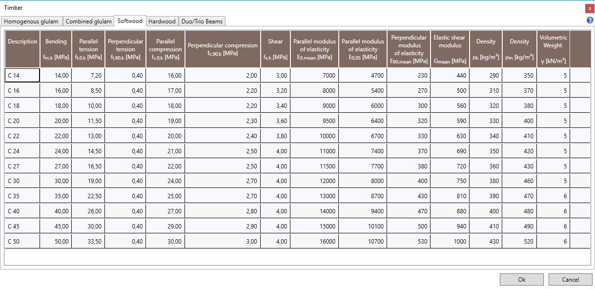
The tables provide the mechanical properties values of different strength classes>:
-
fm,k: Bending strength;
-
ft,0,k: Parallel tension strength;
-
ft,90,k: Perpendicular tension strength;
-
fc,0,k: Parallel compression strength;
-
fc,90,k: Perpendicular compression strength;
-
fv,k: Shear strength;
-
E0,mean: Mean value of the parallel modulus of elasticity;
-
E0,05: Characteristic value of parallel modulus of elasticity;
-
E90,mean: Mean value of the perpendicular modulus of elasticity;
-
G,mean: Mean value of the elastic shear modulus;
-
ρ,k: Density (characteristic value);
-
ρ,m: Density (mean value);
-
γ: Volumetric weight.
4.1.1.3 Duo/Trio Beams:
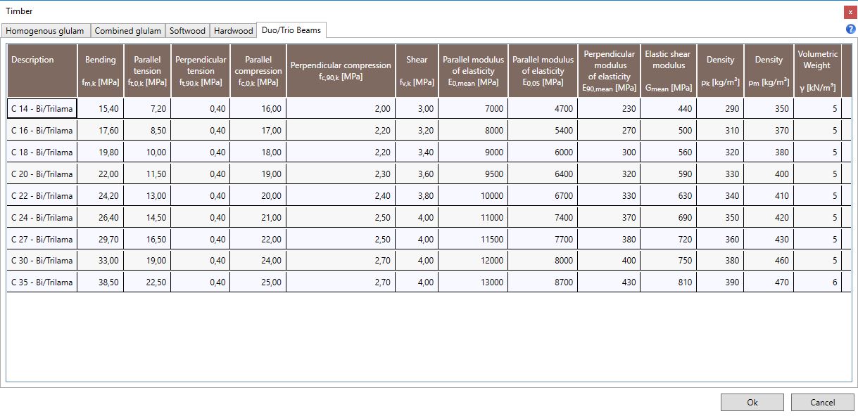
The tables provide the mechanical properties values of different strength classes>:
-
fm,k: Bending strength;
-
ft,0,k: Parallel tension strength;
-
ft,90,k: Perpendicular tension strength;
-
fc,0,k: Parallel compression strength;
-
fc,90,k: Perpendicular compression strength;
-
fv,k: Shear strength;
-
E0,mean: Mean value of the parallel modulus of elasticity;
-
E0,05: Characteristic value of parallel modulus of elasticity;
-
E90,mean: Mean value of the perpendicular modulus of elasticity;
-
G,mean: Mean value of the elastic shear modulus;
-
ρ,k: Density (characteristic value);
-
ρ,m: Density (mean value);
-
γ: Volumetric weight.
4.1.1.4 BauBuche GL:

The tables provide the mechanical properties values of different strength classes>:
-
fm,k: Bending strength;
-
ft,0,k: Parallel tension strength;
-
ft,90,k: Perpendicular tension strength;
-
fc,0,k: Parallel compression strength;
-
fc,90,k: Perpendicular compression strength;
-
fv,k: Shear strength;
-
E0,mean: Mean value of the parallel modulus of elasticity;
-
E0,05: Characteristic value of parallel modulus of elasticity;
-
E90,mean: Mean value of the perpendicular modulus of elasticity;
-
G,mean: Mean value of the elastic shear modulus;
-
ρ,k: Density (characteristic value);
-
ρ,m: Density (mean value);
-
γ: Volumetric weight.
4.1.2 Panels

The Panels command allows the user to consult the performance data of different panel types:
4.1.2.1 Plywood
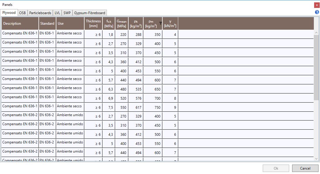
The tables provide the mechanical properties values of different usage classes (dry conditions, humid conditions and exterior conditions), according to EN 636-1, EN 636-2 and EN 636-3:
-
Thickness;
-
fv,k : Shear strength;
-
Gmean: Mean value of Shear modulus;
-
ρk: Characteristic density;
-
ρm: Mean density;
-
γ: Volumetric weight.
4.1.2.2 OSB
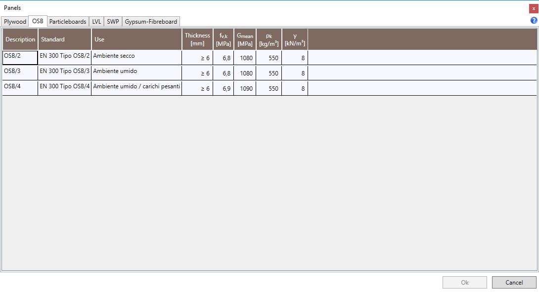
The tables provide the mechanical properties values of different usage classes: panels OSB/2 in dry conditions, panels OSB/3 in humid conditions and panels OSB/4 for humid conditions and heavy loads according to EN 300:
-
Thickness;
-
fv,k: Shear strength;
-
Gmean: Mean value of Shear modulus;
-
ρk: Characteristic density;
-
γ: Volumetric weight.
4.1.2.3 Particleboards
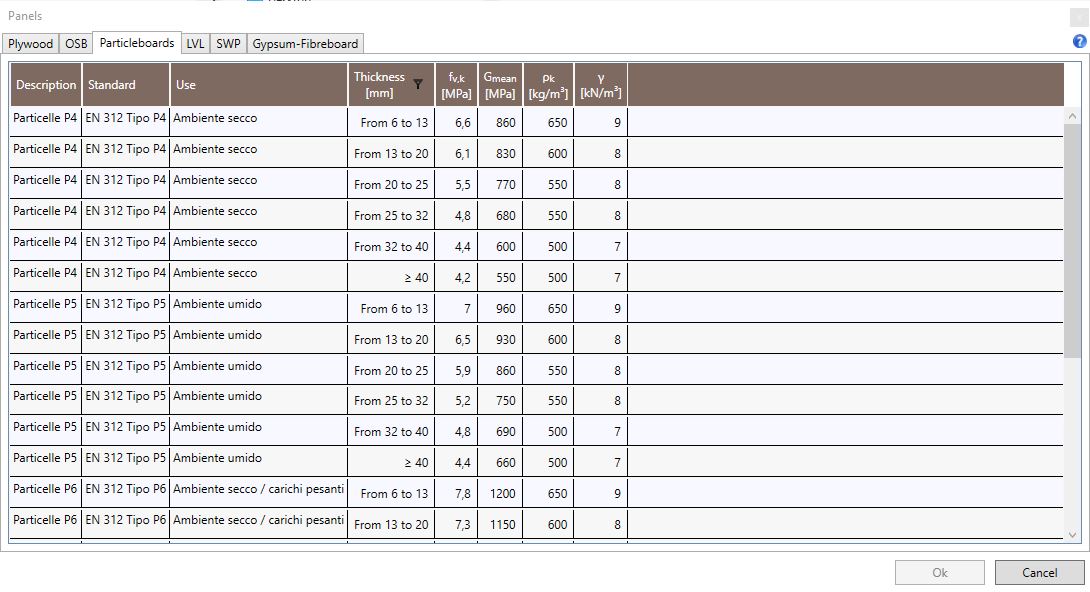
The tables provide, according to EN 312,the mechanical properties values of different particleboards: P4 type for the use in dry conditions, P5 in humid conditions, P6 for heavy loads and humid conditions:
-
Thickness;
-
fv,k: Shear strength;
-
Gmean: Mean value of Shear modulus;
-
ρk: Characteristic density;
-
γ: Volumetric weight.
4.1.2.4 LVL (Laminated Veneer Lumber)
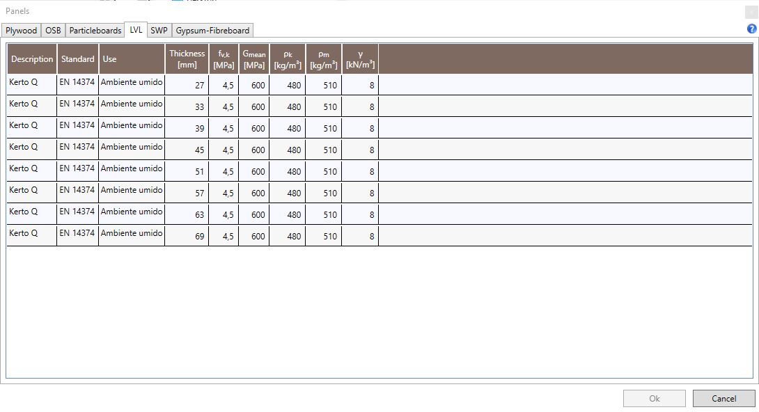
The table provides, in addition to the product description and the use conditions, the following mechanical and physical properties values according to EN 14374:
-
Thickness;
-
fv,k: Shear strength;
-
Gmean: Mean value of Shear modulus;
-
ρk: Characteristic density;
-
ρm: Mean density;
-
γ: Volumetric weight.
4.1.2.5 SWP (Solid Wood Panels)
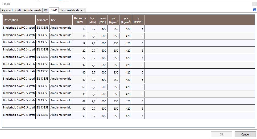
The table provides, in addition to the product description and the use conditions, the following mechanical and physical properties values according to EN 13353:
-
Thickness;
-
fv,k: Shear strength;
-
Gmean: Mean value of Shear modulus;
-
ρk: Characteristic density;
-
ρm: Mean density;
-
γ: Volumetric weight.
4.1.2.6 Gypsum-Fibreboard
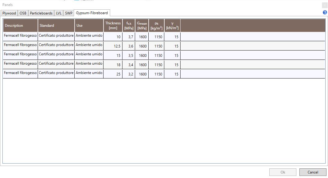
The table provides, in addition to the product description and the usage conditions, the following mechanical and physical properties values:
-
Thickness;
-
fv,k: Shear strength;
-
Gmean: Mean value of Shear modulus;
-
ρk: Characteristic density;
-
γ:Volumetric weight.
4.1.2.7 Gypsum-Plasterboard

The table provides, in addition to the product description and the usage conditions, the following mechanical and physical properties values:
-
Thickness;
-
fv,k: Shear strength;
-
Gmean: Mean value of Shear modulus;
-
ρk: Characteristic density;
-
γ:Volumetric weight.
4.1.3 CLT

The CLT command provides the access to the tables reporting the available stratigraphies of the CLT panels (Cross Laminated Timber). There are two types of panels depending on the external layers orientation:
External layers parallel to the longitudinal direction

External layers parallel to the transversal direction
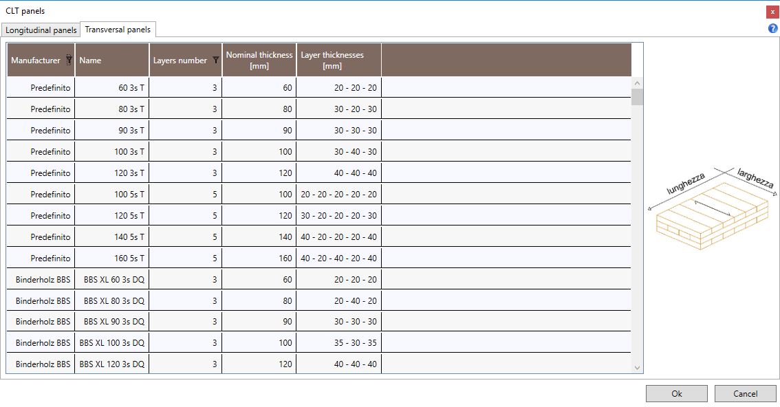
The table provide the following product data:
-
Manufacturer;
-
Code describing the product. For instance 90 3s L indicates the nominal thickness, the number of layers, the external layers orientation (L: longitudinal orientation; T: transverse orientation);
-
Number of layers;
-
Nominal thickness;
-
Layers stratigraphy.
4.1.4 Fasteners

The Fasteners command allows the user to consult the tables reporting the technical data of the following products:
4.1.4.1 Smooth nails
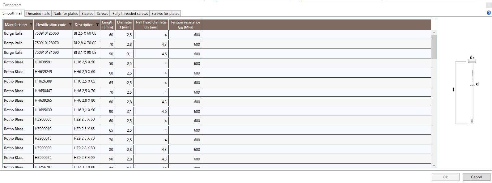
The table provides the manufacturer, the identification code, the description and the following geometrical and mechanical values:
-
l: Length;
-
d: Diameter;
-
dh: Head diameter;
-
fu,k: Tension strength.
4.1.4.2 Threaded nails
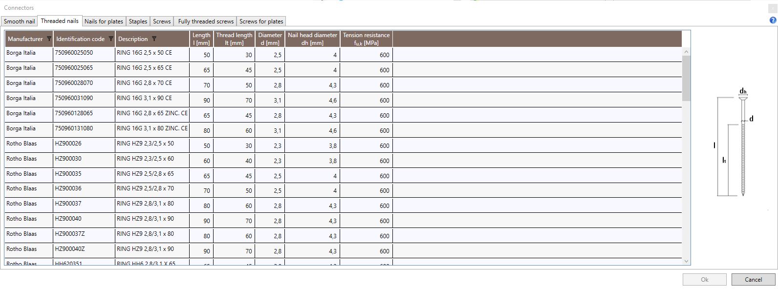
The table provides the manufacturer, the identification code, the description and the following geometrical and mechanical values:
-
l: Length;
-
lt: Threaded nails;
-
d: Diameter;
-
dh: Head diameter;
-
fu,k: Tension resistance.
4.1.4.3 Anker nails
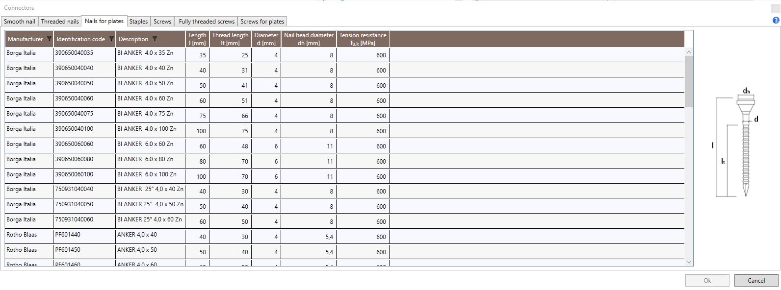
The table provides the manufacturer, the identification code, the description and the following geometrical and mechanical values:
-
l: Length;
-
lt: Threaded nails;
-
d: Diameter;
-
dh: Head diameter;
-
fu,k: Tension resistance.
4.1.4.4 Staples
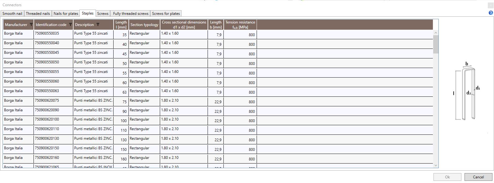
The table provides the manufacturer, the identification code, the description and the following geometrical and mechanical values:
-
l: Length;
-
Section typology;
-
Cross sectional dimensions d1 x d2;
-
b: length;
-
fu,k: tension strength.
4.1.4.5 Screws
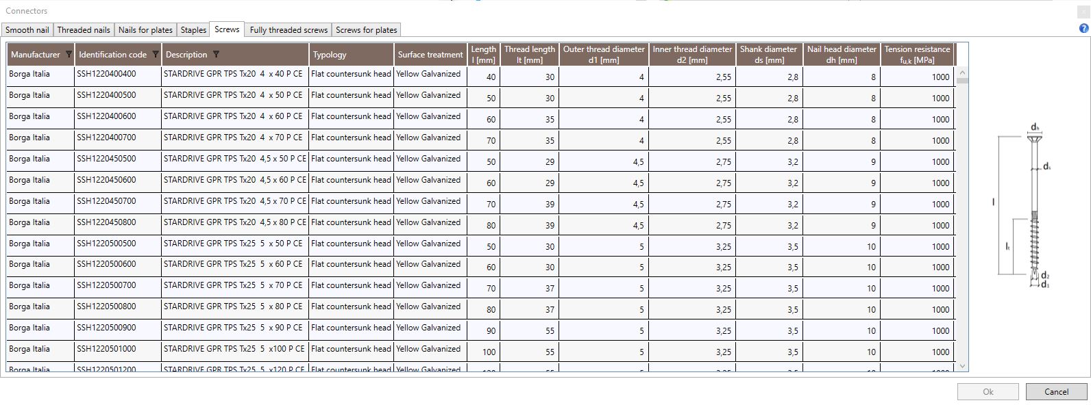
The table provides the manufacturer, the identification code, the description and the following geometrical and mechanical values:
-
Typology;
-
Surface treatment;
-
l: length;
-
lt: Threaded nails;
-
d1: Outer thread diameter;
-
d2: Inner thread diameter;
-
ds: Shank diameter;
-
dh: Nail head diameter;
-
fu,k: Tension strength.
4.1.4.6 Fully threaded screws
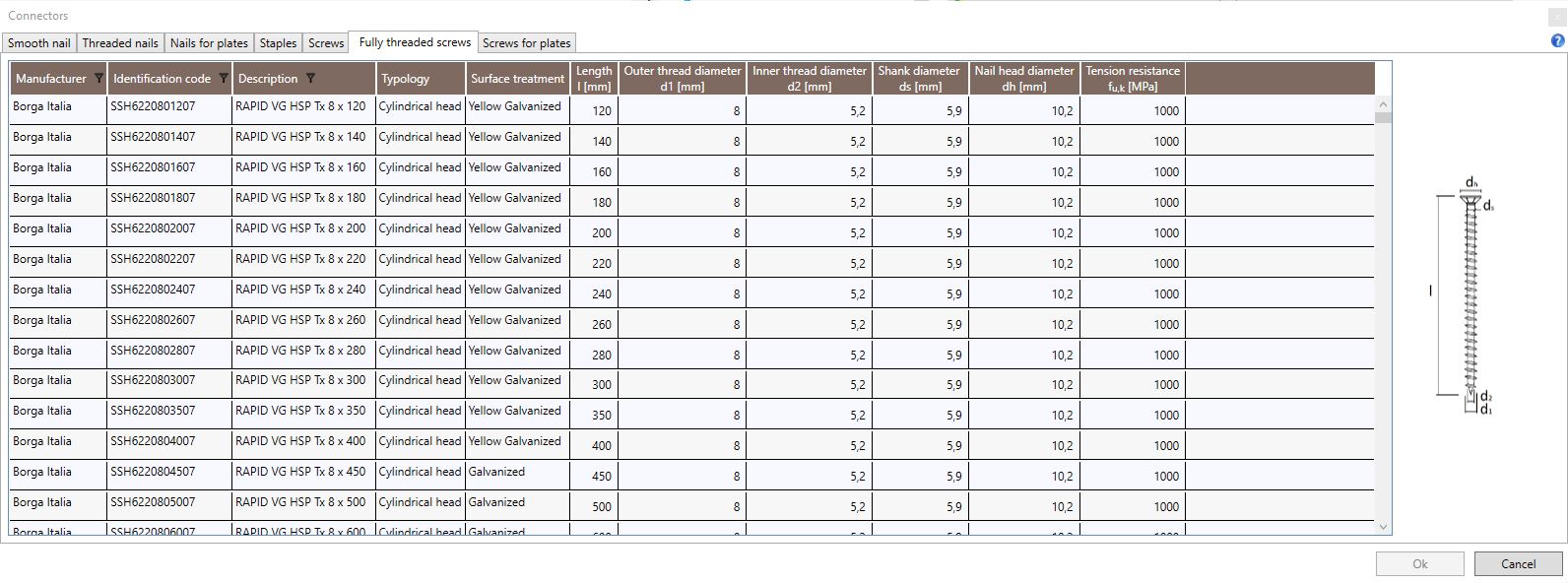
The table provides the manufacturer, the identification code, the description and the following geometrical and mechanical values:
-
Typology;
-
Surface treatment;
-
l: length;
-
d1: Outer thread diameter;
-
d2: Inner thread diameter;
-
ds: Shank diameter;
-
dh: Nail head diameter;
-
fu,k: Tension strength.
4.1.4.7 Screws for plates
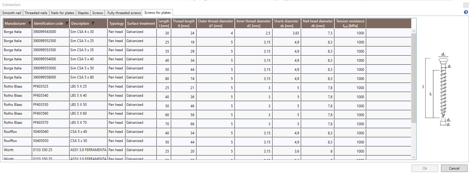
The table provides the manufacturer, the identification code, the description and the following geometrical and mechanical values:
-
Typology;
-
Surface treatment;
-
l: length;
-
lt: Threaded nails;
-
d1: Outer thread diameter;
-
d2: Inner thread diameter;
-
ds: Shank diameter;
-
dh: Nail head diameter;
-
fu,k: Tension strength.
4.1.5 Connection elements

The Connection elements command provides the access to the databases of the tensile and shear connections used for restrainig the wall elements at their base.
4.1.5.1 Hold-Down
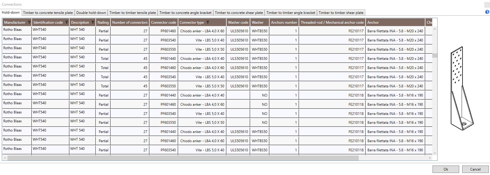
The table provides the manufacturer, the identification code and the description of the connection components (hold-down, fasteners, washer (if any), threaded rod/mechanical anchor and chemical anchor) and the following installation information:
-
Nailing: partial or total;
-
Number of connectors: number of fasteners in the steel-to-timber connection;
-
Number of anchors: number of anchors in the steel-to-concrete connection.
4.1.5.2 Timber to concrete tensile plate
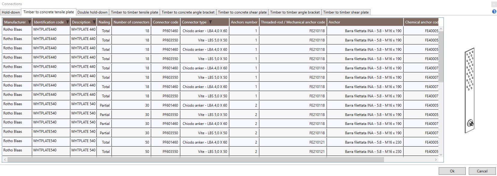
The table provides the manufacturer, the identification code, the description of the connection components (steel plate, fasteners, threaded rod/mechanical anchor and chemical anchor) and the following installation information:
-
Nailing: partial or total;
-
Number of connectors: number of fasteners in the steel-to-timber connection;
-
Number of anchors: number of anchors in the steel-to-concrete connection.
4.1.5.3 Double hold-down
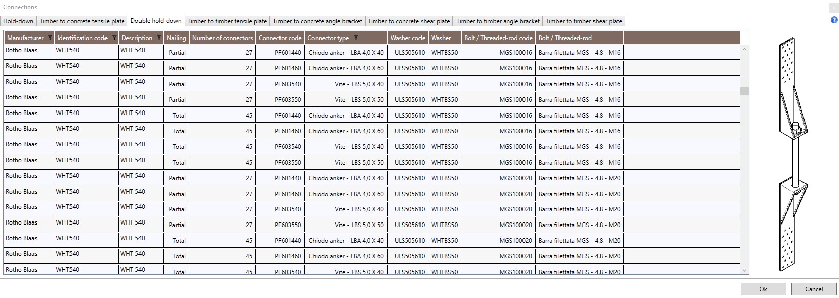
The table provides the manufacturer,the identification code, the description of the connection components (hold-down, fasteners, washer (if any) and bolt/threaded rod) and the following installation information:
-
Nailing: partial or total;
-
Number of connectors: number of fasteners in the steel-to-timber connection.
4.1.5.4 Timber to timber punched steel plates for tension forces
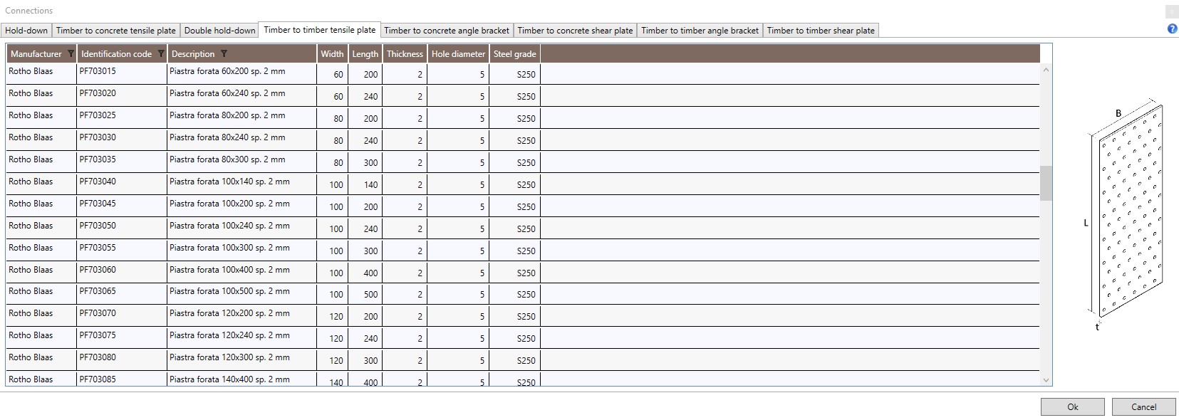
The table provides the manufacturer,the identification code, the description of the plate and the following geometrical and mechanical values:
-
B: width;
-
L: length;
-
t: thickness;
-
Holes diameter;
-
Steel grade.
4.1.5.5 Timber to concrete angle bracket
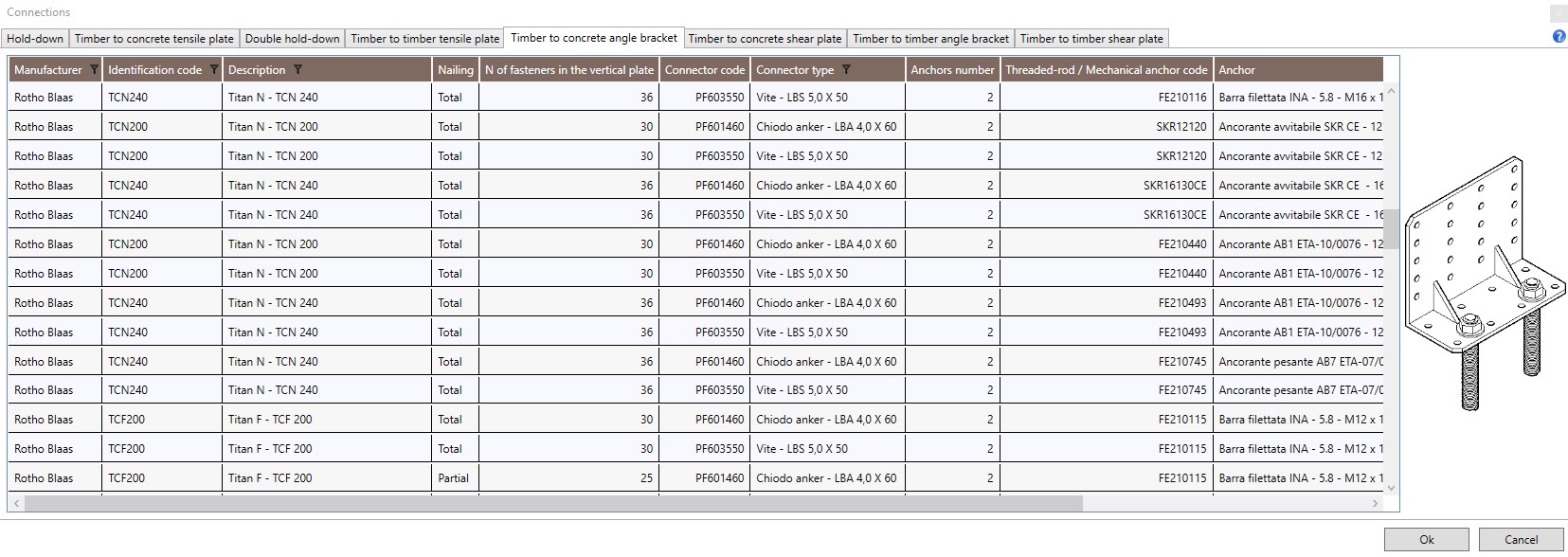
The table provides the manufacturer,the identification code, the description of the connection components (angle bracket, fasteners, threaded rod/mechanical anchor and chemical anchor (if any)) and the following installation information:
-
Nailing: partial or total;
-
Number of connectors: number of fasteners in the steel-to-timber connection;
-
Number of anchors: number of anchors in the steel-to-concrete connection.
4.1.5.6 Timber to concrete shear plate
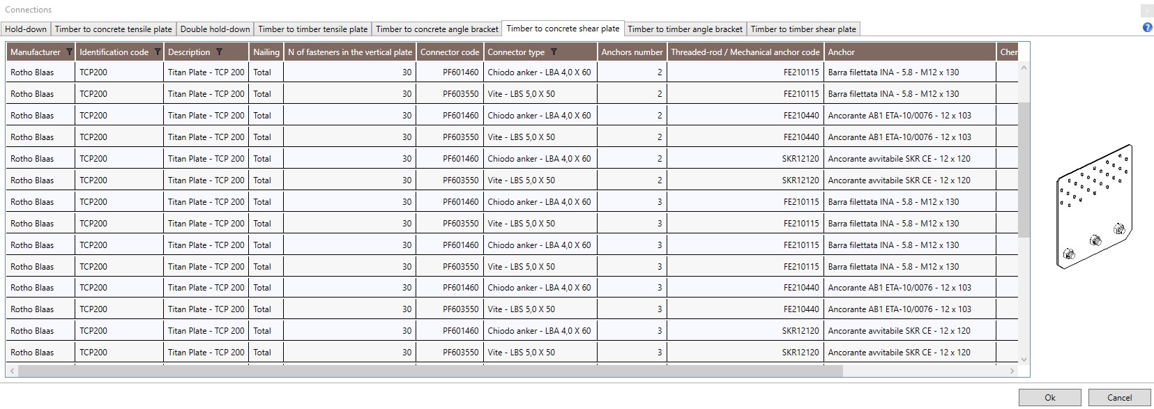
The table provides the manufacturer,the identification code, the description of the connection components (steel plate, fasteners, threaded rod/mechanical anchor and chemical anchor (if any)) and the following installation information:
-
Nailing: partial or total;
-
Number of connectors: number of fasteners in the steel-to-timber connection;
-
Number of anchors: number of anchors in the steel-to-concrete connection.
4.1.5.7 Timber to timber angle bracket
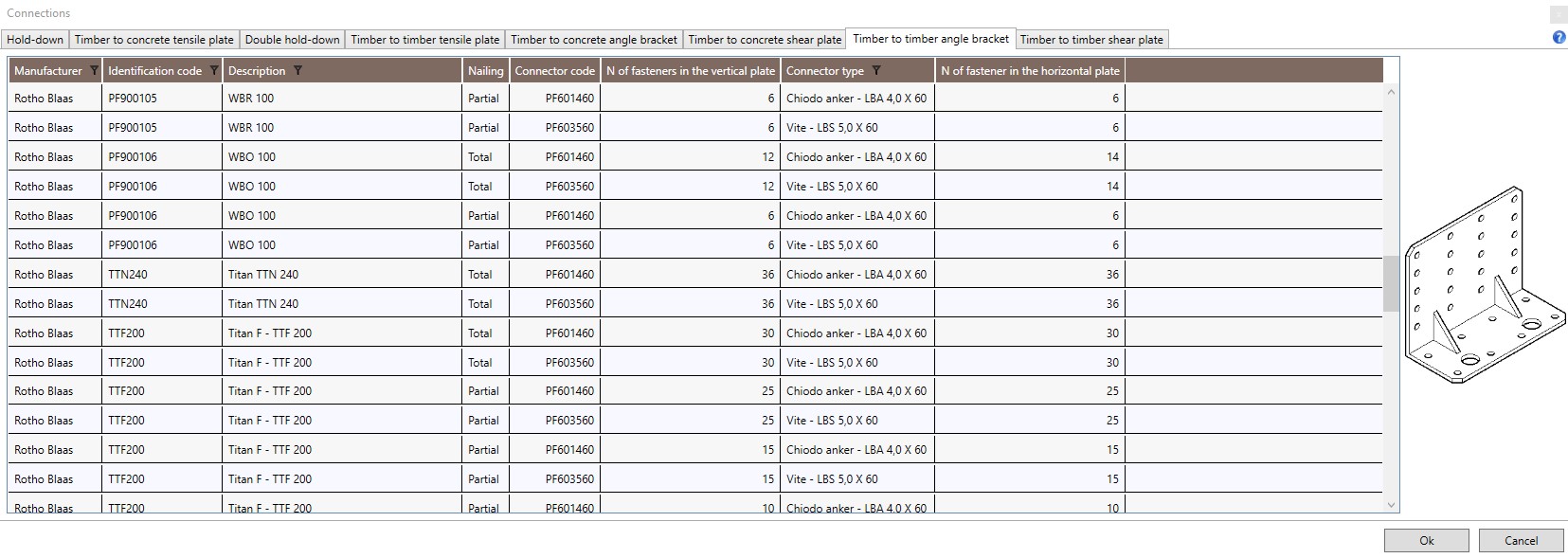
The table provides the manufacturer,the identification code, the description of the connection components (angle bracket, fasteners on the vertical and on the horizontal flange) and the following installation information:
-
Nailing: partial or total;
-
Number of connectors in the vertical plate: number of fasteners in the steel-to-timber connection of the vertical flange of the bracket;
-
Number of connectors in the horizontal plate: number of fasteners in the steel-to-timber connection of the horizontal flange of the bracket.
4.1.5.8 Timber to timber punched steel plates for shear forces
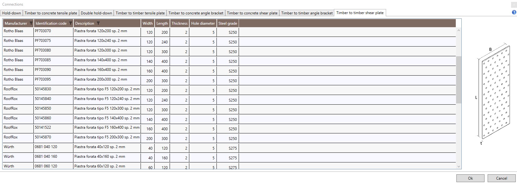
The table provides the manufacturer,the identification code, the description of the plate and the follownig mechanical and geometrical proprieties:
-
B: width;
-
L: length;
-
t: thickness;
-
Holes diameter;
-
Steel grade.
4.1.6 Anchors

The Anchors command allows the user to consult the tables reporting the technical data of the following products:
4.1.6.1 Chemical anchors
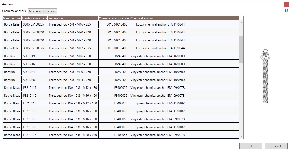
The table provides the manufacturer, the identification code and the description of threaded rods and chemical anchors.
4.1.6.2 Mechanical anchors
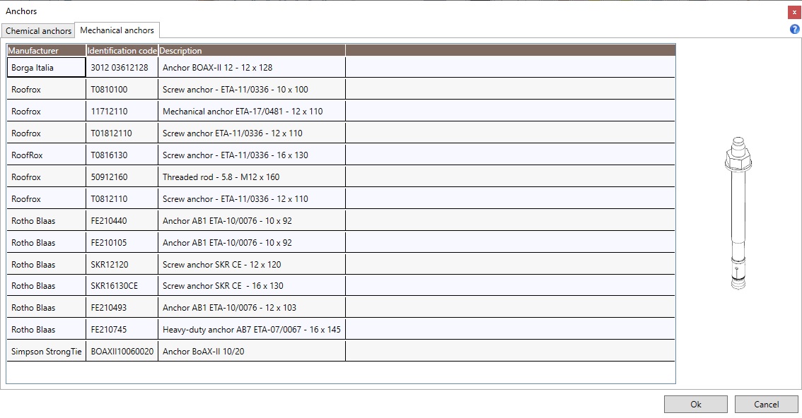
The table provides the manufacturer, the identification code and the description of mechanical anchors.
4.1.7 Steel profiles

The Steel profiles command allows the user to consult the tables reporting the technical data of the most wide-spread steel cross-sections.
4.1.7.1 European open sections
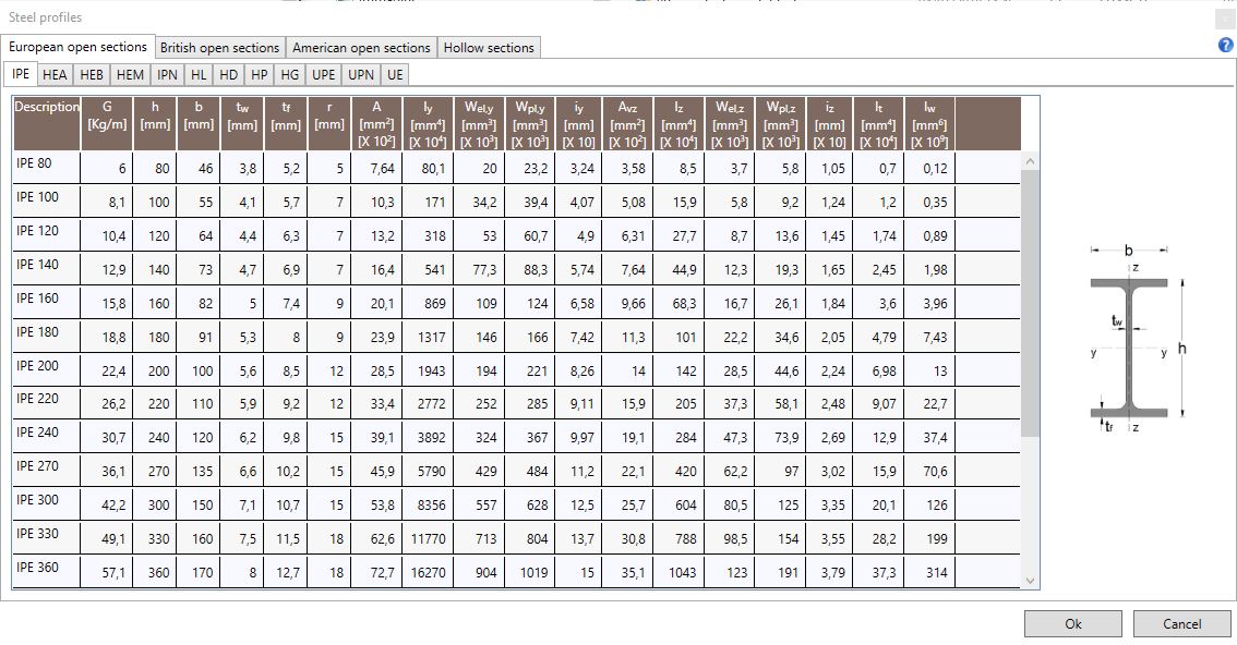
The available tables report the geometrical and inertial characteristics of IPE, HEA, HEB, HEM, IPN, HL, HD, HP, HG, UPE, UPN and UE cross-sections.
4.1.7.2 British open sections
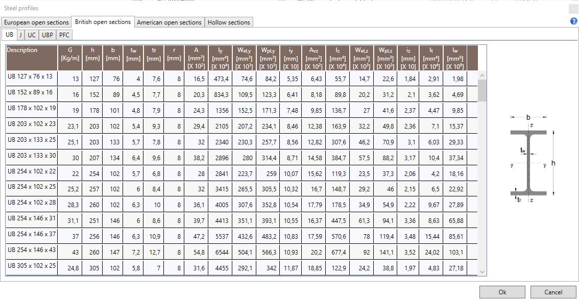
The available tables report the geometrical and inertial characteristics of UB, J, UC, UBP ans PFC cross-sections.
4.1.7.3 American open sections
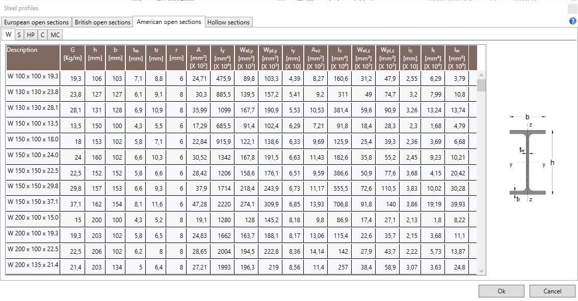
The available tables report the geometrical and inertial characteristics of W, S, HP, C and MC cross-sections.
4.1.7.4 Hollow sections
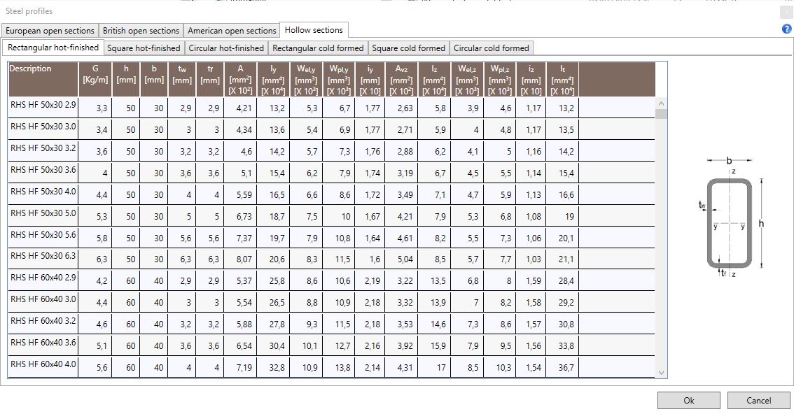
The available tables report the geometrical and inertial characteristics of rectangular hot-finished sections, square hot-finished sections, circular hot-finished sections, rectangular cold formed sections, square cold formed sections and circular cold formed sections.
4.2 Elements
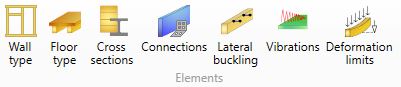
The Elements menu allows the user to fully define the geometrical and mechanical characteristics of the structural elements and of the walls connectors.
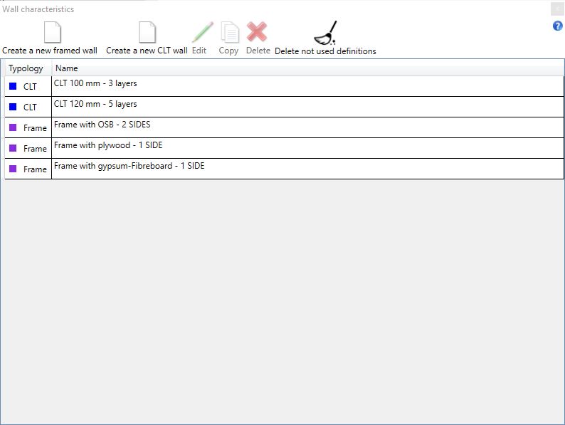
4.2.1 Wall type

The command Wall Type allows the user to define a wall type and to modify or copy an existing one. The user can also consider the predefined walls.
4.2.1.1 Framed wall
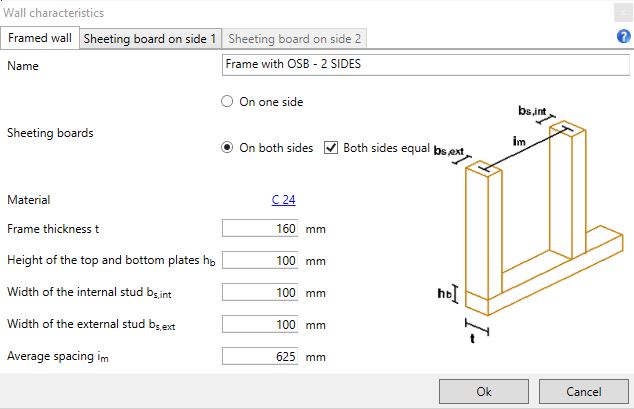
The Create a new framed wall command allows the user to define a new wall type specifying the geometrical and the mechanical properties of the frame and of the sheeting boards. In the first window the user can:
-
assign a name to the wall type;
-
define the number if sides with sheeting boards;
-
define the frame material by selecting from the databases;
-
define the geometrical proprieties of the frame elements.
The geometrical proprieties of the frame elements are:
-
Frame thickness t;
-
Height of the top and bottom frame hb ;
-
Width of the internal stud bs,int;
-
Width of the external stud bs,ext;
-
Average spacing im.
The user can define the geometrical and mechanical characteristics of the sheeting board by selecting the windows Sheeting board on side1/side2:
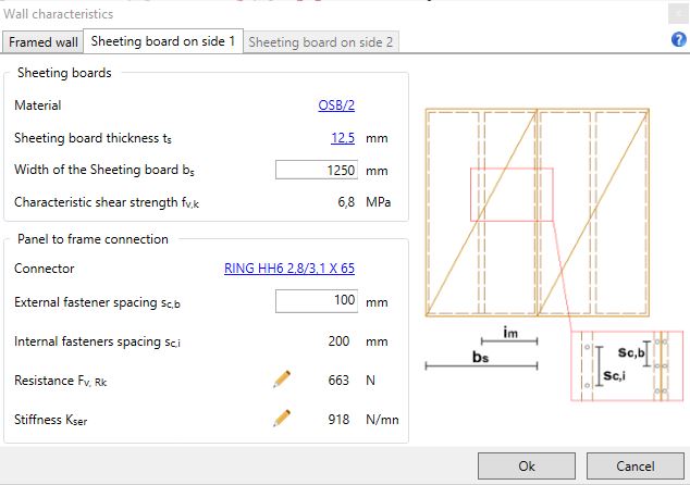
In these windows the user can assign:
-
the sheeting board material by selecting from the databases;
-
the connectors type from the databases;
-
the geometrical characteristics of the boards;
-
the external fasteners spacing.
The geometrical characteristics of the boards are:
-
Sheeting boards thickness ts;
-
Sheeting boards width bs.
The internal fasteners spacing sc,i is deduced from the external one sc,b according to UNI EN 1995-1-1: 2005, point 10.8.2: sc,i = min(2sc,b ; 300 mm).
The total strength of the board-frame connection Fv,Rk, shown in the window, is deduced according to UNI EN 1995-1-1: 2005, point 8.2.2.
The fasteners stiffness Kser , shown in the window, is calculated according to UNI EN 1995-1-1: 2005, point 7.1.
Note:

Left-clicking the mouse on this icon, the user can change the value shown immediately to the right of the icon itself.
4.2.1.2 CLT
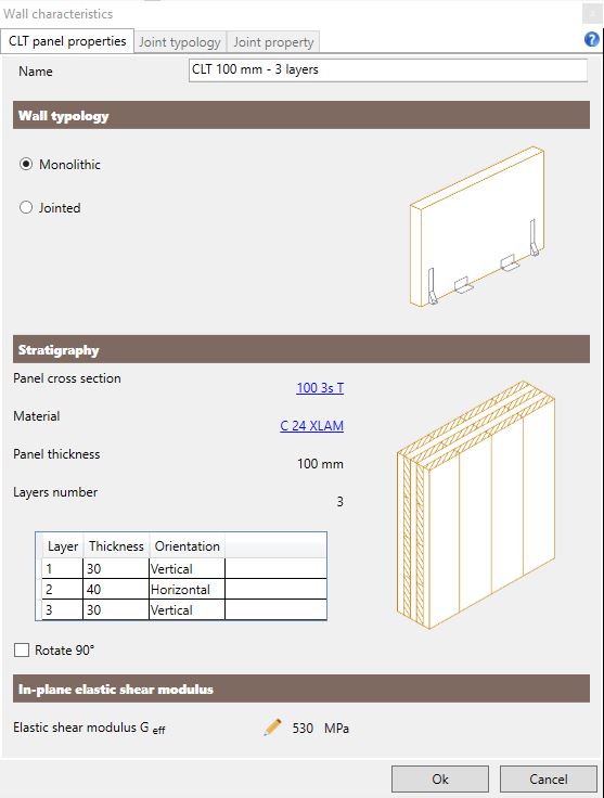
The command Create CLT wall allows the user to create a new wall type specifying the geometrical and mechanical characteristics of the CLT panels. In the first window the user has to:
-
select the wall typology between monolithic and jointed;
-
assign a name to the wall type;
-
select the panel stratigraphy and the panel material from the databases.
The user can rotate by 90 degrees the orientation of the panel layers.
According to the selection, the software calculates the shear modulus Geff with reference to the model proposed in the publication Verification of CLT-plates under loads in plane - Bogensperger T. Moosbrugger T. e Silly". The user can also modify the proposed value on the basis of experimental results or more accurate models.
In case of jointed walls, the user can define the joint type and its proprieties in the following windows:
Joint typology
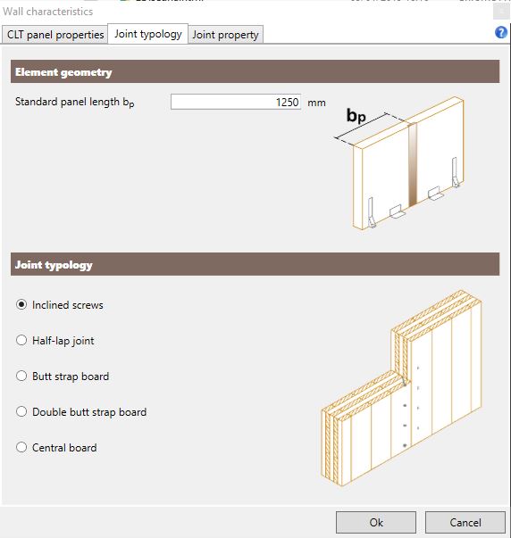
The user can define:
-
the joint typology;
-
the standard panel length bp.
The available joint typologies are:
-
joint with inclined screws (45°);
-
half-lap joint;
-
joint with butt strap board;
-
joint with double butt strap board;
-
joint with central board.
Joint property
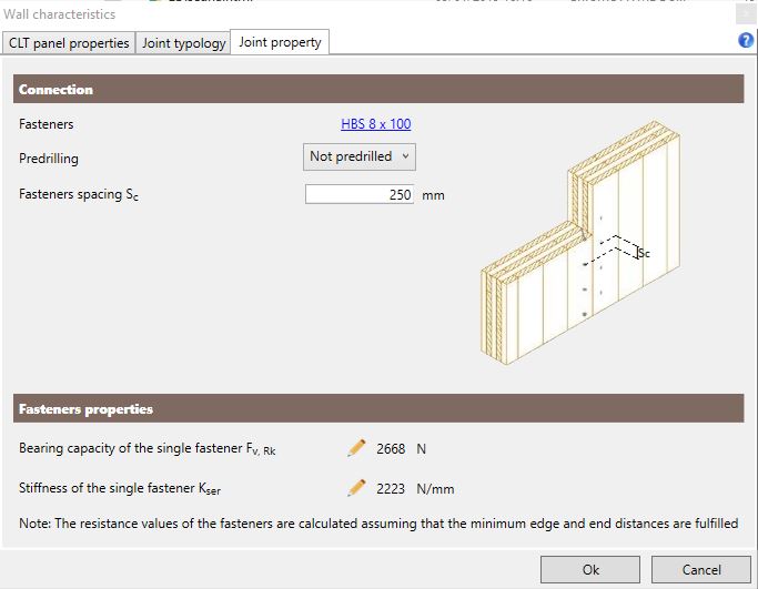
The user can define:
-
the fastener typology from the database;
-
the fasteners spacing Sc.
The bearing capacity of the single fastener Fv,Rk, provided in the dialog box, is calculated according to the UNI EN 1995-1-1: 2005, point 8.2.2.
The stiffness of the single fastener Kser , provided in the dialog box, is calculated according to the UNI EN 1995-1-1: 2005, point 7.1.
4.2.2 Floor type

The command Floor type allows the user to define a floor type and to modify or copy an existing one. The user can also consider the predefined types: joist floor, solid wood floor and CLT floor.
4.2.2.1 Joists floor
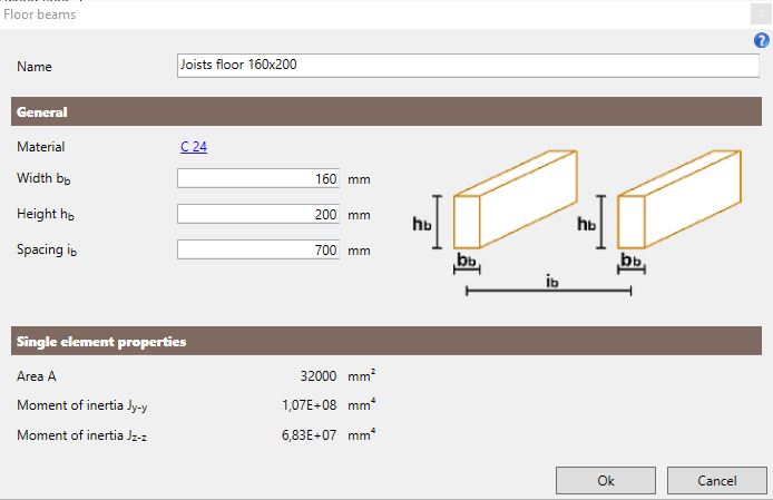
The Create a new joist floor command allows the user to create a new floor type and to define the joists mechanical and geometrical characteristics. In the dialog box the user can:
-
assign a name to the new floor;
-
define the beam material from the database;
-
define the beams geometrical proprieties.
The geometrical proprieties of the beams are:
-
joist width bb;
-
joist height hb;
-
Spacing between the joists ib.
The assumed value of the inertial proprieties are shown in the dialog box.
4.2.2.2 Solid wood floor
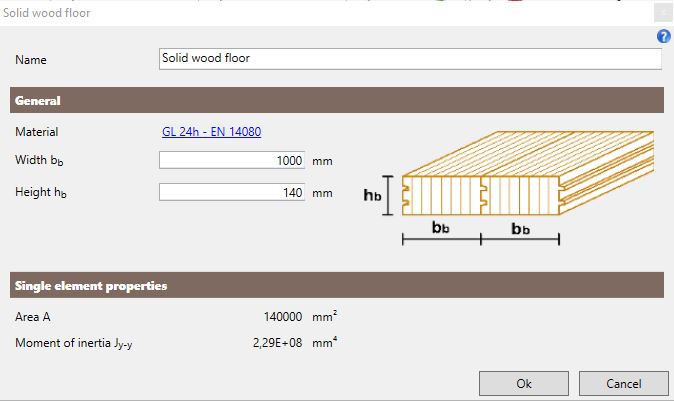
The command Create a Solid wood floor allows the user to create a new solid wood floor type and to define the mechanical and geometrical proprieties of the single element. In the dialog box the user can:
-
assign a name to the new floor;
-
define the panels material from the database;
-
define the geometrical proprieties of the glulam panels.
The user has to define the following geometrical proprieties:
-
Panel width bb;
-
Section height of the panel hb.
The area value and inertial proprieties are provided in the dialog box.
4.2.2.3 CLT floor
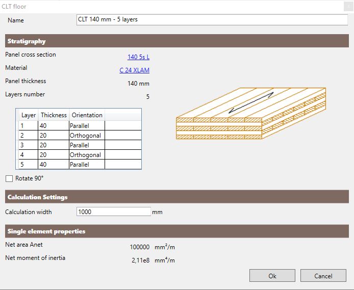
The command Create a CLT floor allows the user to define a new CLT floor type and to define the mechanical and geometrical proprieties of the CLT panels.In the dialog box the user can:
-
assign a name to the new floor;
-
choose the panels stratigraphy from the database;
-
choose the material, if needed, from those available;
-
define the orientation of the external layers: parallel or orthogonal to the calculation direction;
-
define the calculation width that is the spacing between the calculation lines used to discretise the floor.
The dialog box provides the inertial proprieties: the net area and the net moment of inertia.
4.2.3 Timber cross section

The command Cross section allows the user to define a beam or column cross-section made of timber or steel and to modify or copy an existing one. The user can also consider a predefined cross section.
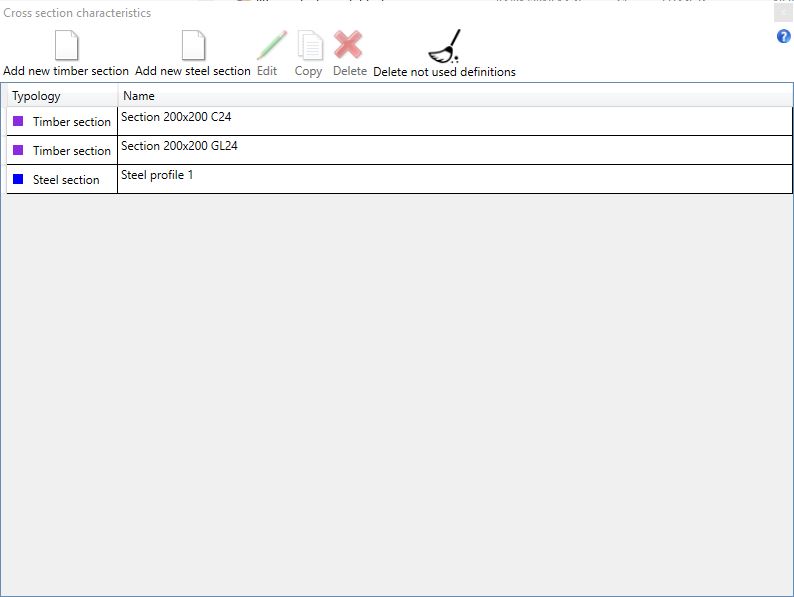
If the user clicks on the Add new timber section command, he will define a new timber section:
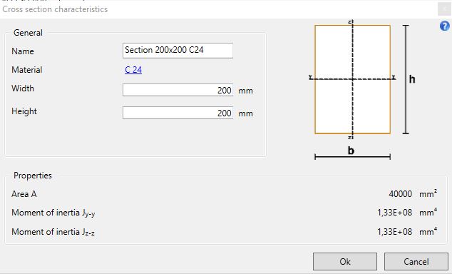
In the dialog box the user can:
-
assign a name to the new section;
-
assign the section material from the database;
-
assign the geometrical proprieties of the cross-section.
The dialog box provides the inertial proprieties: area and inertial moments about the main axes.
If the user clicks on the Add new steel section command, he will define a new steel section:
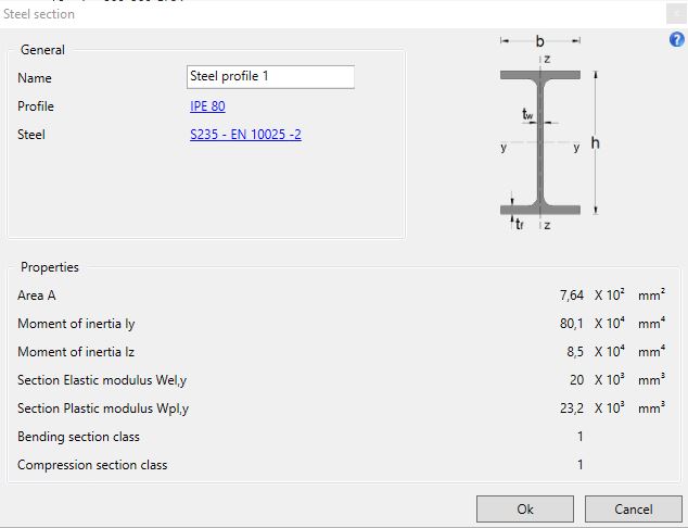
In the dialog box the user can:
-
assign a name to the new section;
-
choose the steel profile from the database;
-
choose the steel type.
The dialog box provides the inertial proprieties: area, inertial moments, elastic and plastic modulus about the main axes and cross-section classification in bending and in compression.
4.2.4 Connections

The command is used to define a new connection type and to modify or to copy an existing one. The user can also choose a predefined connection.
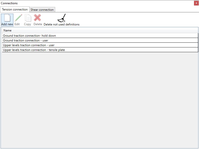
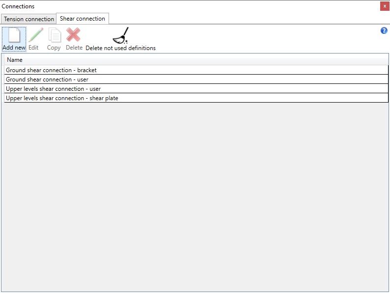
By selecting the Add new command, the user can create a new connection type:
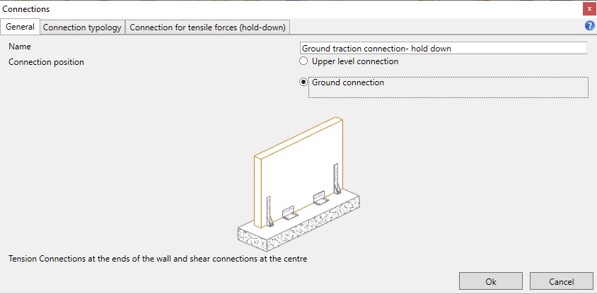
In the first dialog box the user can:
-
assign a name to the new definition;
-
choose the connection position (ground connection or upper level connection).
Note: calculation of the bearing capacity of the nailing - values from certifications
For connections whose certificate provides the characteristic value of the nailing resistance (hold down, double hold down, timber to concrete tensile plate, timber to concrete angle bracket, timber to timber angle bracket, timber to concrete shear plate) the following applies.
Rk indicates the characteristic value of the bearing capacity of the nailing assumiong that the minimum edge and end distances are fulfilled and with reference to a characteristic density of the timber equal to 350 kg/m3. For a density of the used material lower than 350 kg/m3, in the calculation phase the resistance of the nailing will be corrected using the following eqaution Rk,dens = Rk · (ρk / 350)2. In the calculation the resistance of the nailing will be evaluated using the actual density of the wood used.
Note: calculation of the resistance of the nailing - calculated values (Johansen theory)
For connections in which the value of the bearing capacity of the nailing is calculated using the theory of Johansen (timber to timber tensile plates and timber to timber shear plates) the following applies.
Rk indicates the characteristic value of the bearing capacity of the nailing assuming that the minimum edge and end distances are fulfilled and with reference to a characteristic density of the timber equal to 350 kg/m3. In the analysis phase the actual density value will be considered.
The characteristic load-carrying capacity of a steel-to-timber connection depends on the thickness of the steel plates: with reference to the actual thickness of the steel plate, the calculation will be done according to the hypothesis of thick or thin plate or by interpolation between these values.
4.2.4.1 Upper level connection
The next dialog boxes allow the user to fully define the connection properties.
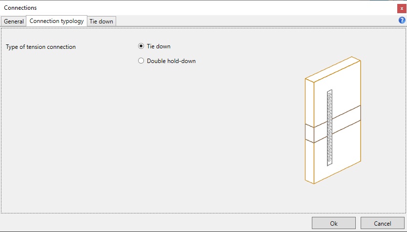
Tension connection Tie down:
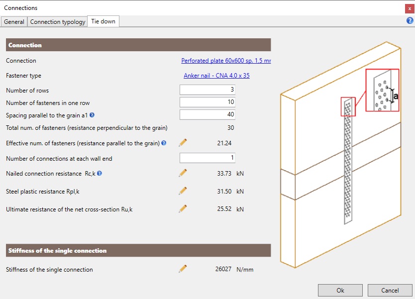
The user can define:
-
the connection type;
-
the fastener type;
-
the number of fasteners (number of rows and number of fasteners in each row);
-
the number of connections at each wall end.
The dialog box provides:
-
the nailed connection resistance Rc,k;
-
the steel plastic resistance Rpl,k;
-
the ultimate resistance of the net cross-section Ru,k;
-
the tensile stiffness value.
Note: use of the total or the effective number of fasteners
The total number of fasteners is used by the software for the calculation of the load-carrying capacity for actions in direction perpendicular to the grain
The effective number of fasteners is used by the software for the calculation of the load-carrying capacity for actions in direction parallel to the grain
For one row of nails or screws with a diameter def less than or equal to 6 mm parallel to the grain, the load-carrying capacity parallel to the grain is calculated using the effective number of fasteners according to 8.3.1.1 (8) - EN 1995-1-1. For one row of screws with a diameter def greater than 6 mm parallel to the grain, the load-carrying capacity parallel to the grain is calculated using the effective number of fasteners according to 8.5.1.1 (4) - EN 1995-1-1. The effective number of fasteners nef,conn assumed in the calculation of the load-carrying capacity of the connection of a punched metal plate is evaluated using the following expression nef,conn = nef,row * nrows where:
-
nrows is the number of rows;
-
nef,row is the effective number of fasteners in a row.
For a CLT wall the following rules apply.
Punched metal plate/punched strap for tension forces
-
If the grain of the external layers of a CLT wall is vertical than the load-carrying capacity of the connection is evaluated using the effective number of fasteners;
-
If the grain of the external layers of a CLT wall is horizontal than the load-carrying capacity of the connection is evaluated using the total number of fasteners.
Punched metal plate for shear forces
-
If the grain of the external layers of a CLT wall is vertical than the load-carrying capacity of the connection is evaluated using the total number of fasteners;
-
If the grain of the external layers of a CLT wall is horizontal than the load-carrying capacity of the connection is evaluated using the effective number of fasteners.
For a framed wall the load-carrying capacity of the connection of a punched metal plate/punched strap is always evaluated using the effective number of fasteners since the direction of the grain (in the stud for tensile force connections and in the bottom/top plate for shear forces connections) is always parallel to the rows of fasteners and to the load direction.
Note: Minimum spacing parallel to the grain
The input limits of the entry field "Spacing parallel to the grain a1" are evaluated assuming that the acting force is parallel to the grain. The value of the spacing parallel to the grain (a1), in fact, is used only for the evaluation of the effective number of fasteners. If the acting force is perpendicular to the grain the load-carrying capacity calculation is performed using the total number of fasteners.
Tension connection Double Hold-down:
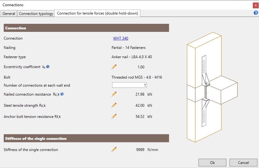
In the dialog box the user can define:
-
the connection type;
-
the eccentricity coefficient;
-
the number of connections at each wall end.
The dialog provides:
-
the fastener type;
-
the bolt type;
-
the nailed connection resistance Rc,k;
-
the Hold-down tensile strength Rs,k;
-
the anchor bolt tension resistance Rt,k;
-
the tensile stiffness.
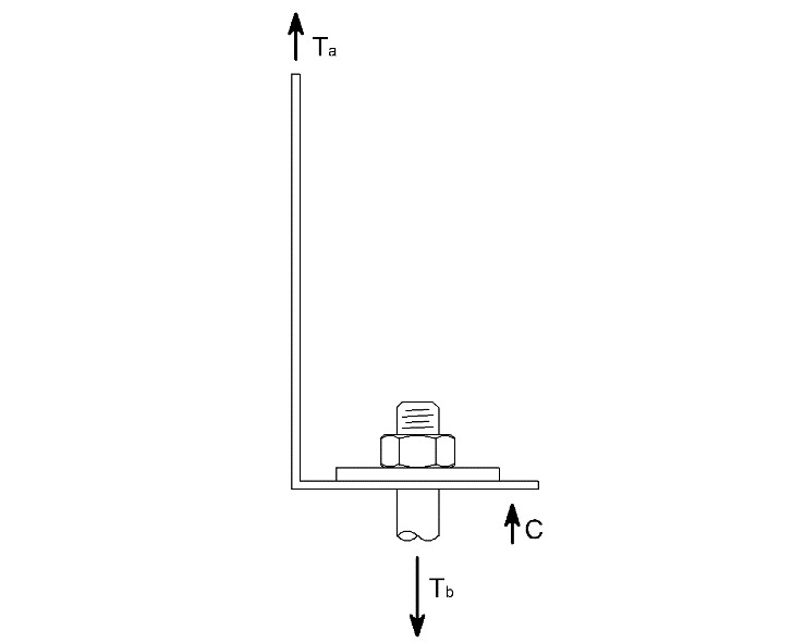
Note: eccentricity coefficient
The tension force acting on the bolt is calculated taking into account the additional moment due to the non-alignment between the external force acting on the vertical flange of the hold down and the bolt itself using a coefficient indicated as kt.
Tb = Ta · kt
where
- Tb: is the tension force acting on the bolt increased by the effect of the eccentricity between the flange and bolt
- Ta: is the tension force acting on the hold down
- kt: is the eccentricity coefficient
Connection for shear forces Timber to timber shear plate:
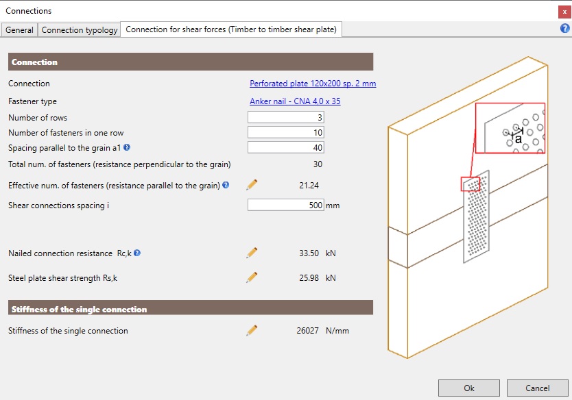
In the dialog box the user can define:
-
the connection type;
-
the fastener type;
-
the number of fasteners (number of rows and number of fasteners in each row);
-
the shear connections spacing i.
The dialog box provides:
-
the nailed connection resistance Rc,k;
-
the steel plate shear strength Rs,k;
-
the shear stiffness.
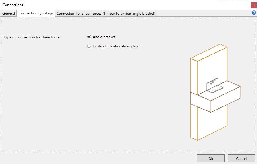
Connection for shear forces Angle bracket:
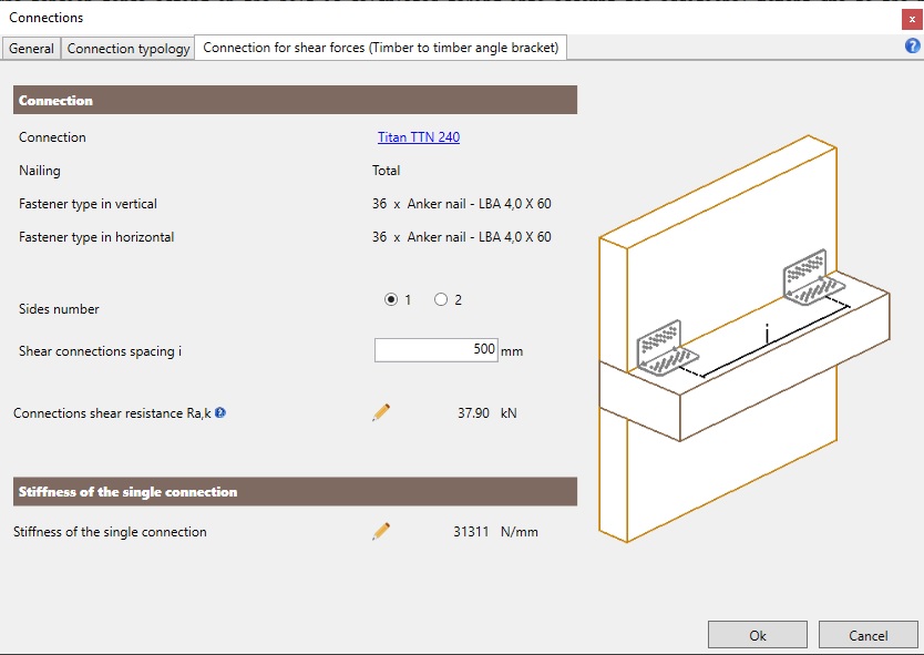
In the dialog box the user can define:
-
the connection type;
-
the number of wall sides (1 or 2) hosting the connection;
-
the shear connections spacing i.
The dialog box provides:
-
the nailing type;
-
the fastener type in the vertical flange;
-
the fastener type in the horizontal flange;
-
the angle bracket shear resistance Ra,k;
-
the shear stiffness.
4.2.4.2 Ground connection
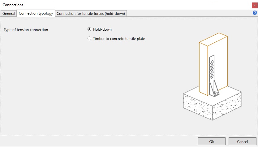
Connection for tensile forces Hold-down:
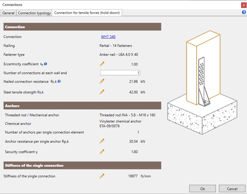
In the dialog box the user can define:
-
the connection type;
-
the eccentricity coefficient;
-
the number of connections at each wall end.
The box provides:
-
the nailing type;
-
the fastener type;
-
the anchors type;
-
the nailed connection resistance Rc,k;
-
the hold-down tensile strength Rs,k;
-
the anchors tensile strength Rp,k;
-
the tensile stiffness.
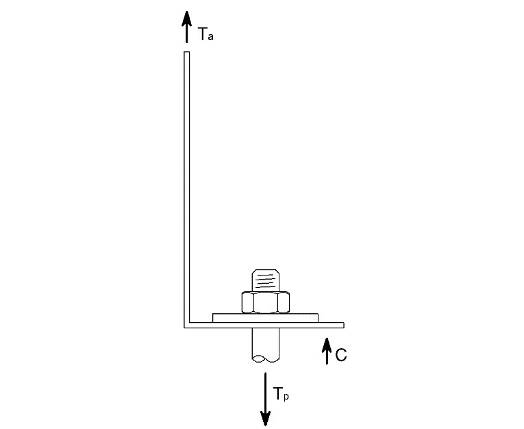
Note: eccentricity coefficient
The tension force acting on the anchors is calculated taking into account the additional moment due to the non-alignment between the external force acting on the vertical flange of the hold down and the anchors themselves using a coefficient indicated as kt.
Tp = Ta · kt
where
- Tp: is the tension force acting on the anchors increased by the effect of the eccentricity between the flange and the anchors
- Ta: is the tension force acting on the hold down
- kt: is the eccentricity coefficient
Connection for tensile forces Timber to concrete tensile plate:
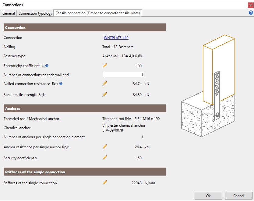
In the dialog box the user can define:
-
the connection type;
-
the eccentricity coefficient kt;
-
the number of connections at each wall end.
The box provides:
-
the nailing type;
-
the fastener type;
-
the anchors type;
-
the nailed connection resistance Rc,k;
-
the plate tensile strength Rs,k;
-
the anchors shear strength Rp,k;
-
the tensile stiffness.
Note: eccentricity coefficient
The shear force acting on the anchors is calculated by means of a correction coefficient, denoted by kt.
Vp = Ta · kt
where
- Vp: is the shaer force acting on the anchors
- Ta: is the tension force acting on the metal plate
- kt: is the eccentricity coefficient
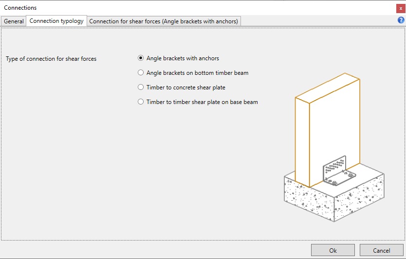
Connection for shear forces Angle bracket with anchors:
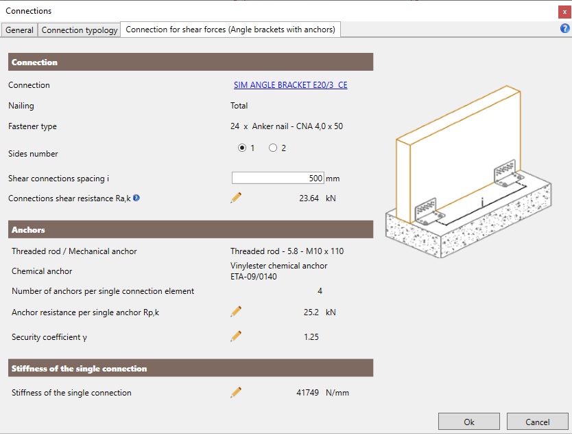
In the dialog box the user can define:
-
the connection type;
-
the number of wall sides (1 or 2) hosting the connection;
-
the shear connections spacing i.
The dialog box provides:
-
the nailing type;
-
the fastener type;
-
the anchors type;
-
the angle bracket shear resistance Ra,k;
-
the anchors shear resistance Rp,k;
-
the shear stiffness.
Connection for shear forces Angle bracket on bottom timber beam:
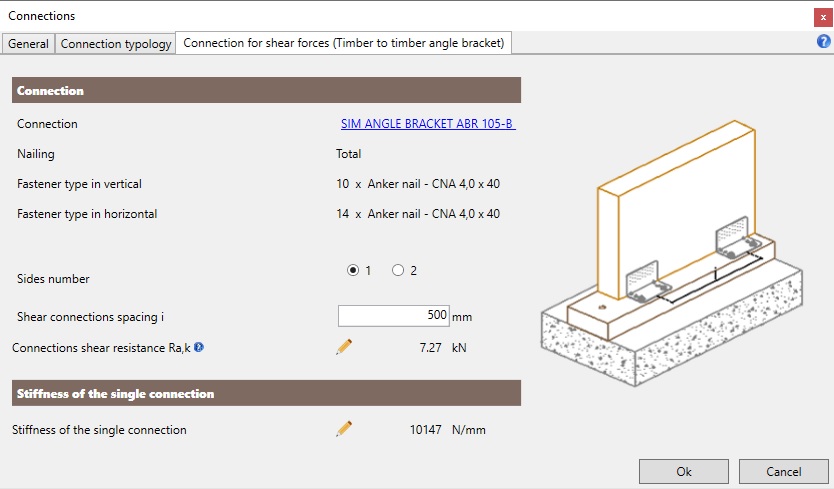
In the dialog box the user can define:
-
the connection type;
-
the number of wall sides (1 or 2) hosting the connection;
-
the shear connections spacing i.
The dialog box provides:
-
the nailing type;
-
the fastener type in the vertical flange;
-
the fastener type in the horizontal flange;
-
the angle bracket shear resistance Ra,k;
-
the shear stiffness.
Connection for shear forcesTimber to concrete shear plate:
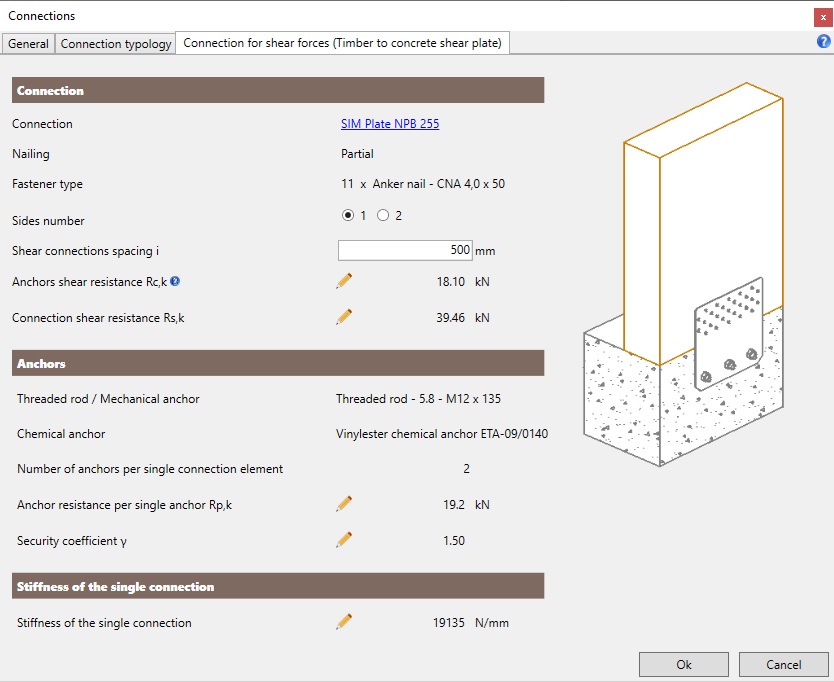
In the dialog box the user can define:
-
the connection type;
-
the number of wall sides (1 or 2) hosting the connection;
-
the shear connections spacing i,
-
the anchors type.
The dialog box provides:
-
the nailed connection resistance Rc,k;
-
the steel plate shear resistance Rs,k;
-
the anchors shear resistance Rp,k;
-
the shear stiffness.
Connection for shear forces Punched steel plate on timber bottom beam:
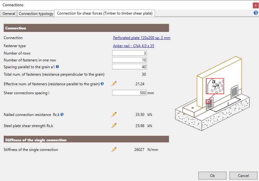
In the dialog box the user can define:
-
the connection type;
-
the fasteners type;
-
the number of fasteners (number of rows and number of fasteners in each row);
-
the shear connections spacing i.
The dialog box provides:
-
the nailed connection resistance Rc,k;
-
the steel plate shear strength Rs,k;
-
the shear stiffness.
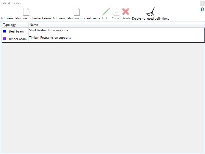
4.2.5 Lateral buckling

The Lateral buckling command allows the user to define the restraint conditions against lateral buckling for timber and steel beams. The user can also modify or copy an existing definition.
If the user clicks the Add new definition for rimber beams command, he will set a new definition for timber beams:
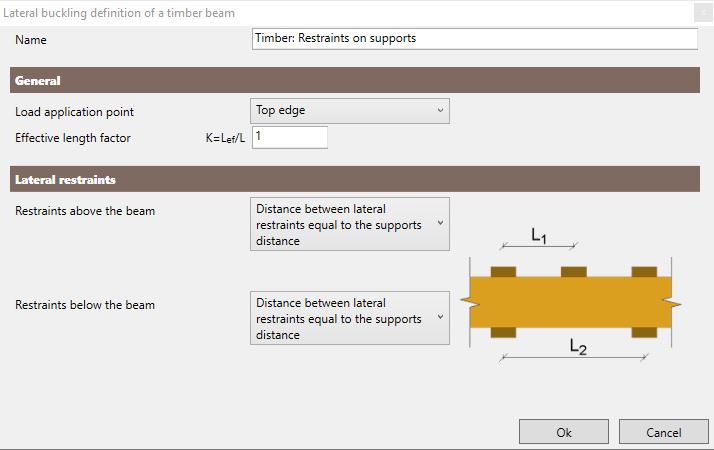
In the dialog box the user can:
-
assign a name to the new definition;
-
choose the load application point;
-
assign the effective lenght factor;
-
define the lateral restraints positions;
If the user clicks the Add new definition for steel beams command, he will set a new definition for steel beams:
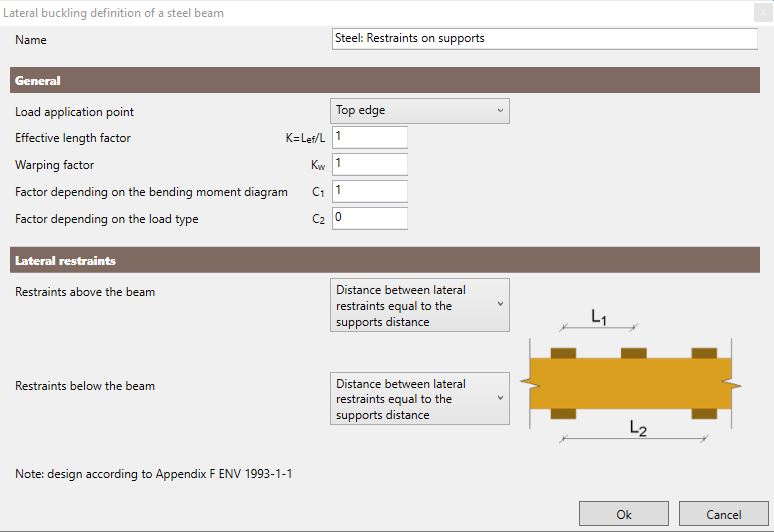
In the dialog box the user can:
-
assign the name to the new group;
-
assign the load application point;
-
assign the effective lenght factor, the warping factor and factors depending on the bending moment diagram and the load type;
-
assign the lateral restraints positions.
For rolled steel channel sections it is assumed that no torsional buckling is occurring.
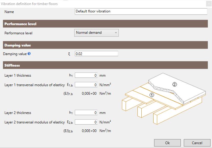
4.2.6 Vibrations

The Vibrations command is used to define some detail properties for the vibration checks on floors. In the dialog box the user can also edit or copy the predefined vibration properties.
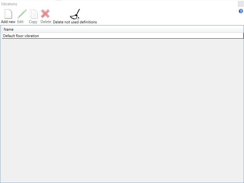
The user can define new vibration properties selecting the command Add new. In the dialog box the can:
-
assign a name to the definition;
-
define the required performance level (Normal demand or High demand);
-
define the damping coefficient;
-
define the transversal stiffness of non-structural elements by setting the thickness and the transversal modulus of elasticity.
The value of the damping coefficient can be indicatively taken as:
-
0,01 for floors without raised floor or in the absence of detailed information;
-
0,02 for XLAM floors or solid wood floors, with raised floor;
- 0,03 for joists floors with raised floor.
4.2.7 Deformation limits

The Deformation limits command allows the user to define the deflection limits for the serviceability checks of floor, roof and beam elements. The user can also edit or copy the predefined deformation limits.
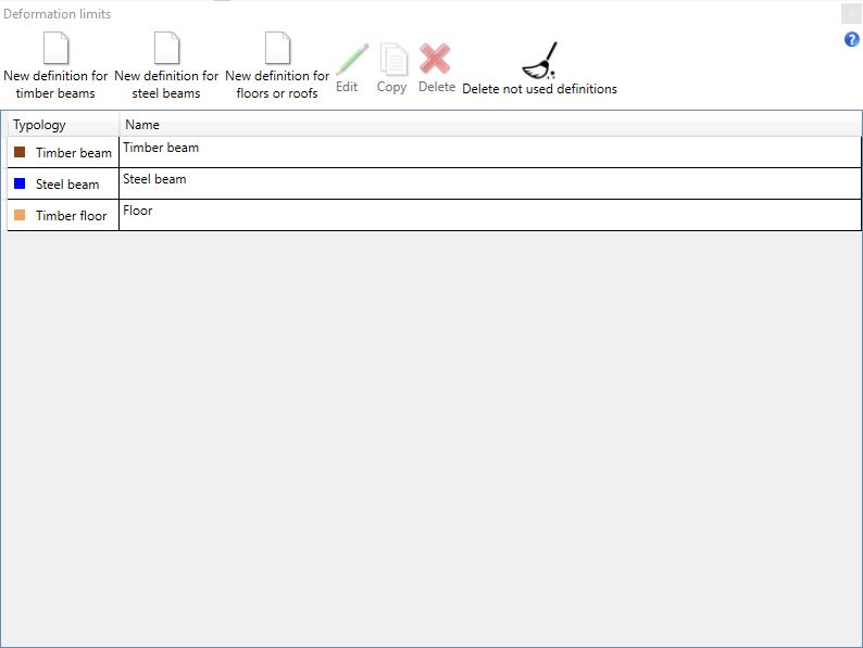
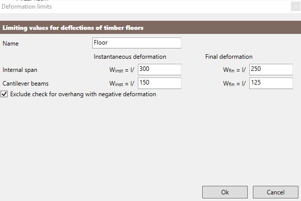
The New definition for timber beams and New definition for floors or roofs commands allows the user to set the deflection limits for timber elements checks. In the dialog box the can:
-
assign a name to the definition;
-
define the defomation limits as a fraction of the span length;
-
choose whether to neglect or not the checks on overhanging elements with negative deformations.
The limits to be set are:
-
instantaneous deformation for not overhanging spans;
-
final deformation for not overhanging spans;
-
instantaneous deformation for overhanging spans;
-
final deformation for overhanging spans.
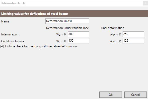
The New definition for steel beams command allows the user to set the deflection limits for steel beams checks. In the dialog box the can:
-
assign a name to the definition;
-
define the defomation limits as a fraction of the span length;
-
choose whether to neglect or not the checks on overhanging elements with negative deformations.
The limits to be set are:
-
deformation under variable loads only for not overhanging spans;
-
final deformation for not overhanging spans;
-
deformation under variable loads only for overhanging spans;
-
final deformation for overhanging spans.
4.3 Loads
4.3.1 Wall loads

The Wall loads command allows the user to define new wall load definitions and to edit or copy the existing ones.
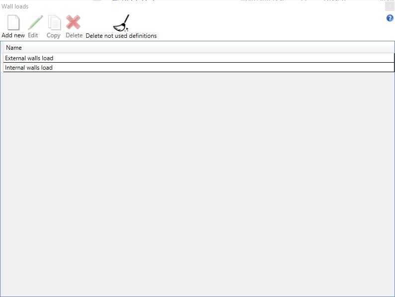
The user can define a new wall load by selecting the command Add new. In the dialog box the user can:
-
assign a name to the load definition;
-
define the wall position (internal or external).
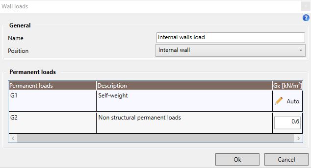
4.3.1.1 Internal wall
If the user defines an Internal wall, he can:
-
edit the self-weight load G1, automatically calculated by the software, by clicking the special icon;
-
assign the non structural permanent load G2 .
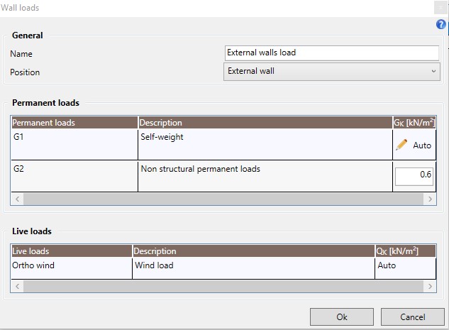
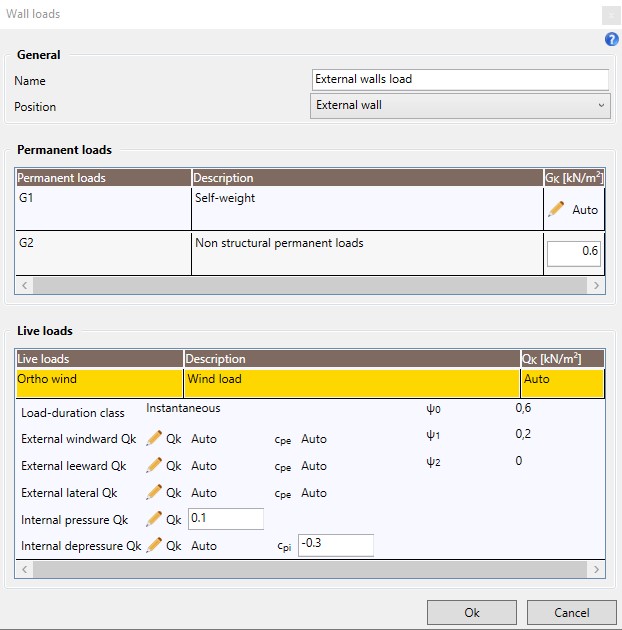
4.3.1.2 External wall
If the user defines an External wall, he can:
-
edit the self-weight load G1, automatically calculated by the software, by clicking the special icon;
-
assign the non structural permanent load G2 .
-
edit the wind load action as specified in the following.
If the reference standard is the Italian one, the Wind load can be automatically calcuated by the software according to the project geolocation and the settings in Project properties/Snow Wind/Wind. In case of other standards (Eurocodes), the Wind load can be automatically calcuated by the software according to the settings in Project properties/Wind following the procedure implemented in the international version of EN 1991-1-4.
Regarding Italian standard, the wind load on walls is defined through its external windward, leeward and lateral components and through the internal pressure and depressure that can be defined according to the following methods:
-
Fully automated calculation: the reference velocity pressure is calculated according to the geolocation of the structure, the exposure coefficient takes into account the exposure category and the appropriate reference height for each wall and each component of the wind load, the dynamic factor is defined by the user in Project properties/Snow Wind/Wind, the external pressure coefficients are computed according to Tab. C3.3.1 of the Circolare 21/01/2019 of the NTC 2018 by taking into account the smallest rectangle circumscribed to the structure plant and the internal pressure coefficients are assumed to be equal to +0.2 and -0.3;
-
Automated calculation with user-defined pressure coefficients: the reference velocity pressure is calculated according to the geolocation of the structure, the exposure coefficient takes into account the exposure category and the appropriate reference height for each wall and each component of the wind load, the dynamic factor is defined by the user in Project properties/Snow Wind/Wind and the external and internal pressure coefficients are defined manually by the user in order to achieve a more accurate local modelling;
-
User-defined setting: the user can set manually the values of each component of the wind load.
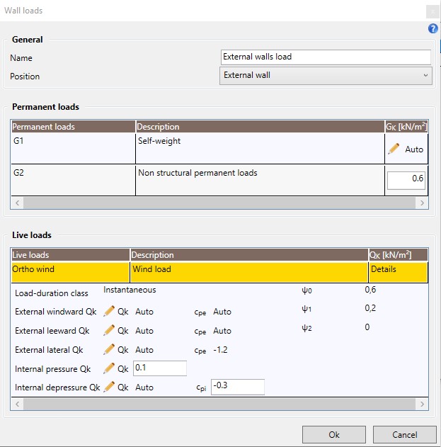
Regarding Eurocodes, the wind load on walls is defined through its external windward, leeward and lateral components and through the internal pressure and depressure that can be defined according to the following methods:
-
Fully automated calculation: the basic velocity pressure is calculated according to the basic wind velocity vb and the air density defined in Project properties/Wind, the exposure factor takes into account the terrain category and the appropriate reference height for each wall and each component of the wind load, the dynamic and the orography factor are defined by the user in Project properties/Wind, the external windward and leeward pressure coefficients cpe,10 are computed according to section 7.2 of EN 1991-1-4 by taking into account the smallest rectangle circumscribed to the structure plant, the external lateral pressure coefficient cpe,10 is assumed equal to -1.2 and the internal pressure coefficients are assumed to be equal to +0.2 and -0.3;
-
Automated calculation with user-defined pressure coefficients: the basic velocity pressure is calculated according to the basic wind velocity vb and the air density defined in Project properties/Wind, the exposure factor takes into account the terrain category and the appropriate reference height for each wall and each component of the wind load, the dynamic and the orography factor are defined by the user in Project properties/Wind, and the external and internal pressure coefficients are defined manually by the user;
-
User-defined setting: the user can set manually the values of each component of the wind load.
4.3.2 Floor loads

The Floor loads command allows the user to define new floor load definitions and to edit or copy the existing ones.
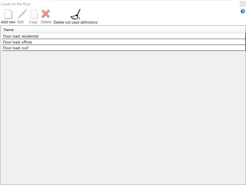
The user can define a new floor load by selecting the command Add new. In the dialog box the user can:
-
assign a name to the floor load definition;
-
define the floor position (internal floor or roof).
4.3.2.1 Internal floor
If the user defines an Internal floor load, he can:
-
edit the self-weight load G1, automatically calculated by the software, by clicking the special icon;
-
assign the non structural permanent load G2 ;
-
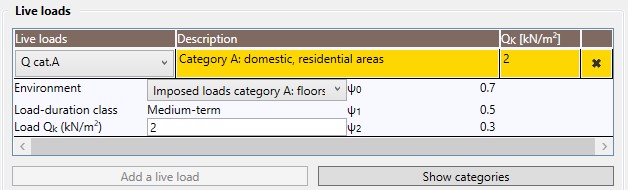
assign the variable load Qk by selecting the relevant category.
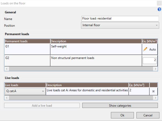
In accordance with the reference standard, the software makes available the live loads included in the standard with their coefficients and the duration class. The user can set the load by selecting the relevant category and sub-category through two drop down menus.
By selecting the Show category command, the table reporting the live loads categories according to the reference standard opens:
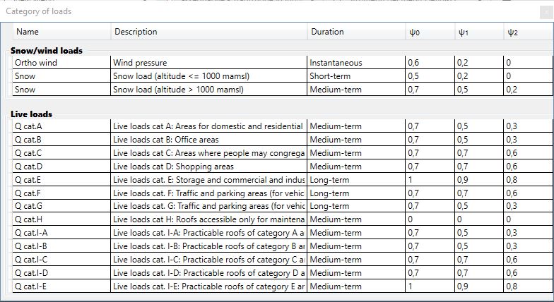
According to the choosen category, the software proposes the load value provided by the standard. The user can increase this value if required.
The user can delete the selected loads by clicking on the "x" button on the right side of the Live loads window:
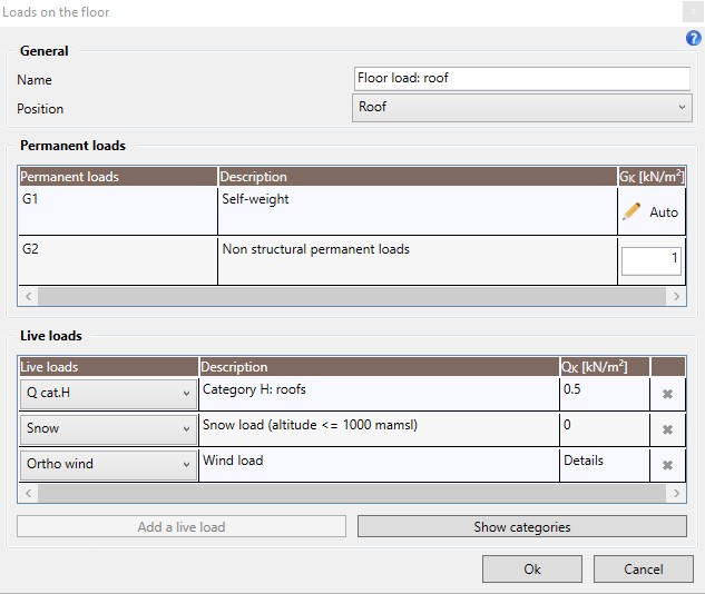
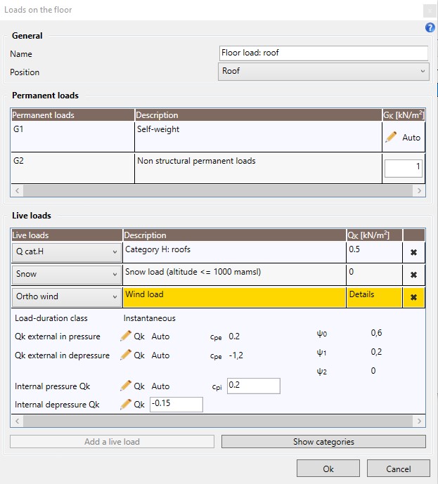
4.3.2.2 Roof
If the user defines a Roof load, he can:
-
edit the self-weight load G1, automatically calculated by the software, by clicking the special icon;
-
assign the non structural permanent load G2 ;
-
assign the variable load Qk by selecting the relevant category;
-
assign the snow load;
-
assign the wind load.
If the reference standard is the Italian one, the wind and snow loads can be automatically calcuated by the software according to the project geolocation and the settings in Project properties/Snow Wind. In case of other standards (Eurocodes), only the wind action values can be automatically calculated by the software.
In case of Italian standard as reference standard, the snow load is calculated according to the structure geolocation, the shape coefficient (computed automatically), the exposure factor (computed automatically) and the thermal coefficient (user-defined). Otherwise, the user can enter manually the value of this load.
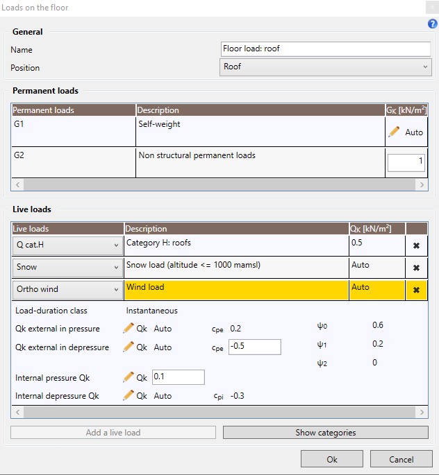
Regarding the wind load, it is defined through its external components in pressure and in depressure and through the internal pressure and depressure that can be defined according to the following methods:
-
Fully automated calculation: the reference velocity pressure is calculated according to the geolocation of the structure, the exposure coefficient takes into account the exposure category and the height of the floor, the dynamic factor is defined by the user in Project properties/Snow Wind/Wind, the external pressure coefficients are assumed equal to +0.2 and -1.1 and the internal pressure coefficients are assumed to be equal to +0.2 and -0.3;
-
Automated calculation with user-defined pressure coefficients: the reference velocity pressure is calculated according to the geolocation of the structure, the exposure coefficient takes into account the exposure category and the height of the floor, the dynamic factor is defined by the user in Project properties/Snow Wind/Wind and the external and internal pressure coefficients are defined manually by the user;
-
User-defined setting: the user can set manually the values of each component of the wind load.
In case of Eurocodes used as reference standard, the Snow load has to be manually defined by the user.
Regarding the wind load, it is defined through its external components in pressure and in depressure and through the internal pressure and depressure that can be defined according to the following methods:
-
Fully automated calculation: the basic velocity pressure is calculated according to the basic wind velocity vb and the air density defined in Project properties/Wind, the exposure factor takes into account the terrain category and the height of the floor, the dynamic and the orography factor are defined by the user in Project properties/Wind, the external pressure coefficients are assumed equal to +0.2 and -1.2 and the internal pressure coefficients are assumed to be equal to +0.2 and -0.3;
-
Automated calculation with user-defined pressure coefficients: the basic velocity pressure is calculated according to the basic wind velocity vb and the air density defined in Project properties/Wind, the exposure factor takes into account the terrain category and the height of the floor, the dynamic and the orography factor are defined by the user in Project properties/Wind and the external and internal pressure coefficients are defined manually by the user;
-
User-defined setting: the user can set manually the values of each component of the wind load.
The user can add a new live loads by selecting the Add a live load command.
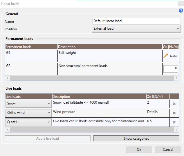
4.3.3 Linear loads

The Linear loads command allows the user to define a linear loads and to edit or copy the existing ones.
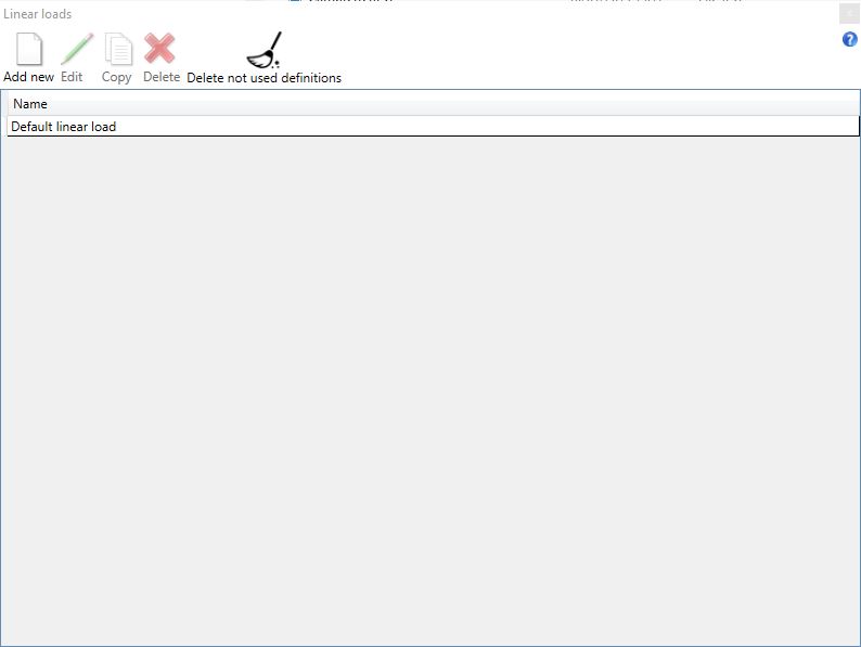
The dialog box is consistent with that of the floor/roof loads mentioned above, please check the previous section for further information.
4.4 Delete not used definitions
The Delete not used definitions allows the user to automatically delete all the Elements and Loads definitions not currently used in the model.
It is not possible to Undo this command.
The software requires that at least a definition is always available for each element/load typology.