5 Project properties tools
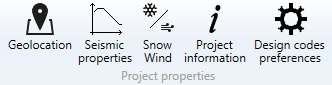
5.1 Geolocation

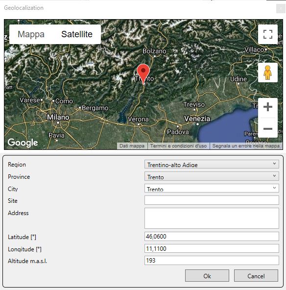
The command Geolocation, that is only available when using the Italian NTC standard as reference standard, allows the user to define the location of the building. The site can be located in the following ways:
-
by using the pointer on the map;
-
by selecting, in the corresponding drop-down menu, the region, the province and the city of the structure site;
-
by typing the coordinates (latitude and longitude) and the altitude in meters above the sea level.
5.2 Seismic properties

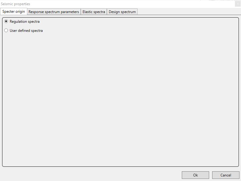
The command Seismic proprieties allows the user to define the seismic parameters required in order to perform the seismic analysis of the structure according to the selected reference standard.
The following dialog boxes differ depending on whether the selected reference standard are the Eurocodes with the relevant National Annex or the Italian standards (Norme Tecniche per le Costruzioni 2008 or 2018).
5.2.1 Eurocodes and relevant Nationa Annex
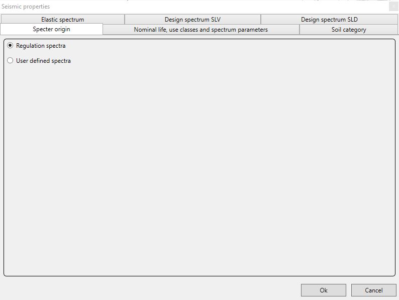
The user has first to choose whether to make reference to the regulation spectra or to user defined spectra.
5.2.1.1 User defined spectra
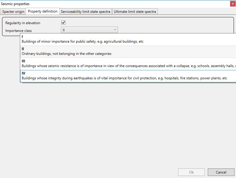
If the user chooses to upload user defined spectra, in the second dialog box he can:
-
indicate whether the strucure is regular in elevation or not;
-
set the importance class according to the Eurocodes definitions.
In the following dialog boxes the user can upload the files, in csv format, of the serviceability and of the ultimate limit state design spectra (already accounting for the relevant behaviour factor).
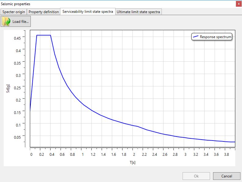
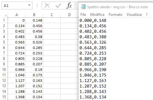
The uploaded file must contain, according to the system settings regarding the decimal and the field separators, the first column with the values on the horizontal axis of the spectrum coordinates and the second column with the values on the vertical axis.
For example, if the system use English-UK settings, the field separator is "," and the decimal separator is ".". If the system use Italian settings, the field separator is ";" and the decimal separator is ",".
5.2.1.2 Regulation spectra - Response spectrum parameters
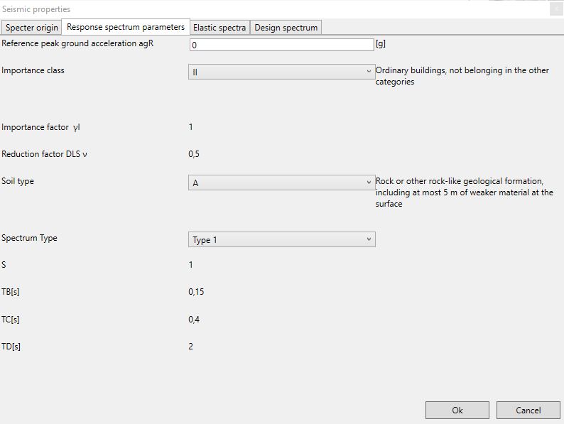
In the dialog box the user can define:
-
the reference peak ground acceleration agR;
-
the importance class from a drop-down menu;
-
the soil type from a drop-down menu.
The dialog box provides:
-
the importance factor and the DLS reduction factor according to the selected importance class;
-
the parameters used to define the elastic response spectrum.
5.2.1.3 Regulation spectra - Elastic spectra
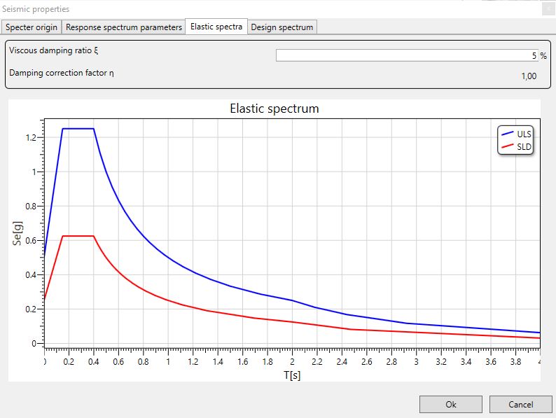
The window displays the elastic spectra corresponding to the Serviceability Limit States and to the Ultimate Limit States. They are defined according to the above mentioned parameters and the formulations provided by EC8.
Moreover, the user can edit:
- the value of the viscous damping ratio ξ (expressed as a percentage) according to the materials, to the structural typology and to the soil category.
The related damping correction factor η modifies the response spectrum in case of ξ different from 5%.
5.2.1.4 Regulation spectra - Design spectrum
The dialog box displays the design spectrum as a red line. This spectrum is obtained by applying the behaviour factor q that takes into account the inelastic dissipative capacity of the structure together with its overstrength and the increase of its period as a result of plasticisation.
In the dialog box the user can:
-
define whether the structure is regular in elevation or not;
-
define the basic value of the behaviour factor q0.
The dialog box provides:
-
the coefficient of regularity in elevation that is equal to 1 in case of regularity in elevation and 0,8 otherwise;
-
the behaviour factor calculated as the product between q0 and the coefficient of regularity in elevation.
5.2.2 Norme Tecniche per le Costruzioni 2008 or 2018
The user has first to choose whether to make reference to the regulation spectra or to user defined spectra.
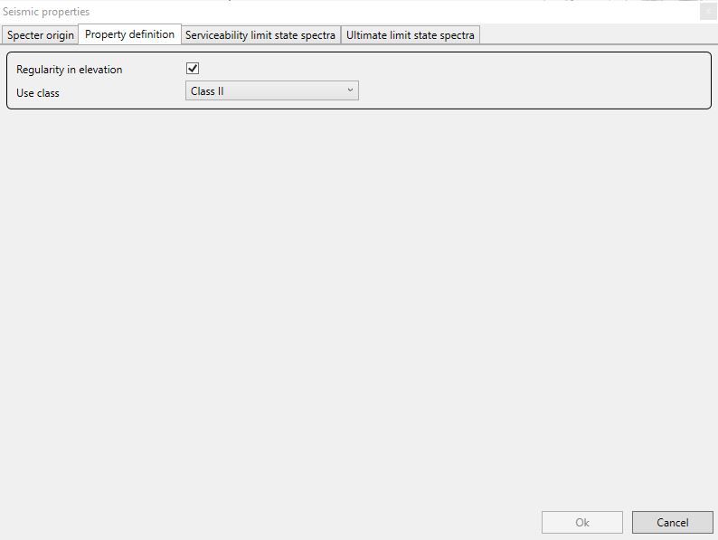
5.2.2.1 User defined spectra
If the user chooses to upload user defined spectra, in the second dialog box he can:
-
indicate whether the strucure is regular in elevation or not;
-
set the usage class according to the NTC definitions.
In the following dialog boxes the user can upload the files, in csv format, of the serviceability and of the ultimate limit state design spectra (already accounting for the relevant behaviour factor).
The uploaded file must contain, according to the system settings regarding the decimal and the field separators, the first column with the values on the horizontal axis of the spectrum coordinates and the second column with the values on the vertical axis.
For example, if the system use English-UK settings, the field separator is "," and the decimal separator is ".". If the system use Italian settings, the field separator is ";" and the decimal separator is ",".
5.2.2.2 Regulation spectra - Nominal life, usage classes and spectrum parameters
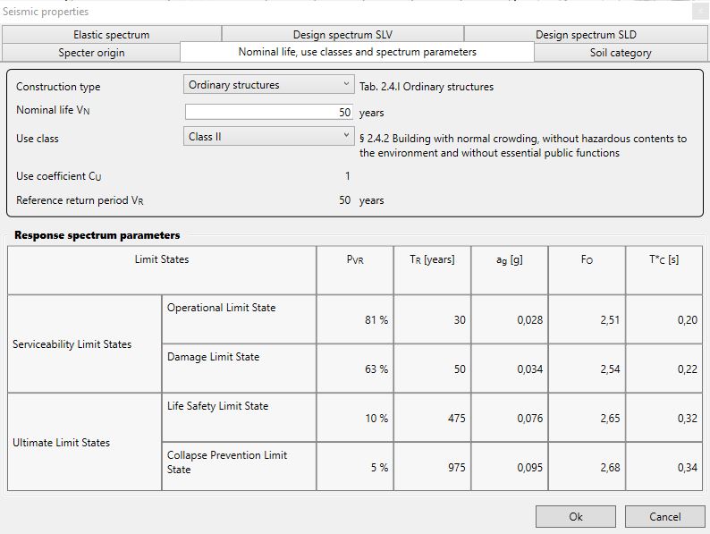
In the dialog box the user can define:
-
the construction type from a drop-down menu;
-
the nominal life VN;
-
the usage class from a drop-down menu.
The dialog box provides:
-
the usage coefficients value CU according to the selected usage class;
-
the reference return period value VR given by the equation VR = VN ·CU;
Then the window shows the parameters, according to the Serviceability Limit States and Ultimate Limit States, used to define the elastic response spectrum:
-
PVR: probability of exceedance in the reference return period;
-
TR: reference return period according to the exceedance probability;
-
ag : design ground acceleration;
-
F0: horizontal spectral acceleration amplification factor;
-
T*C: period value where the spectrum section with constant velocity starts.
5.2.2.3 Regulation spectra - Soil category
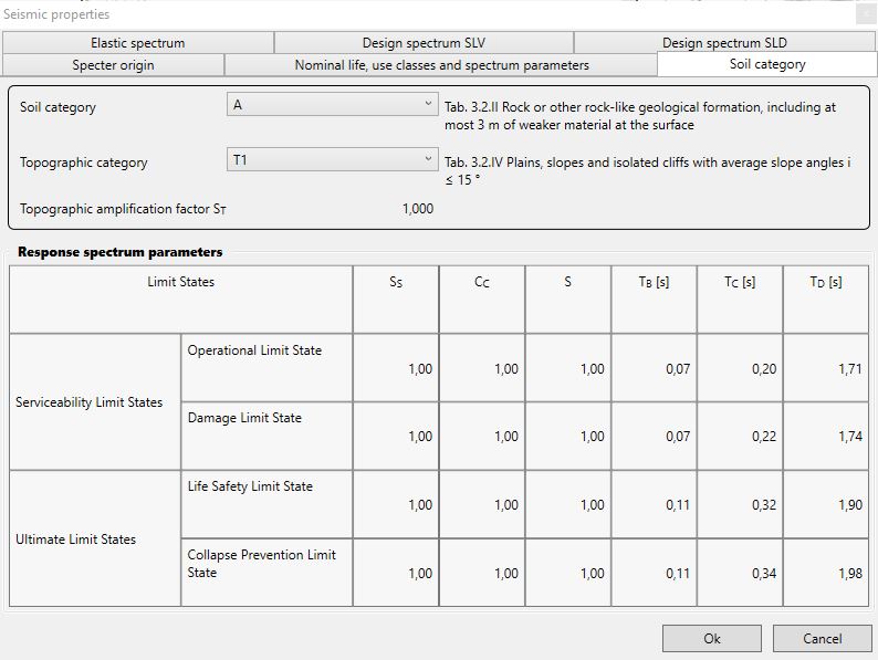
In the dialog box the user can:
-
define the soil category from the drop-down menu;
-
define the topographic category from the drop-down menu;
-
the ratio between the height h of the site and the height H of the hill if relevant.
The dialog box provides the topographic amplification factor ST and the values of the following parameters with reference to the serviceability and to the ultimate limit states:
-
SS: stratigraphic amplification factor;
-
CC: coefficient depending on the category of the subsoil;
-
S: soil factor depending on the soil category and on the topographic category. The parameter is obtained from the formula S = SS·ST;
-
TB: period value where the section with constant acceleration of the spectrum starts. The parameter is obtained from the expression TB = TC/3;
-
TC: period value where this constant acceleration plateau ends. The parameter is defined by the expression TC = CC·T*C;
-
TD: period value where the constant displacement section of the spectrum starts. The parameter is defined by the expression TD = 4,0·ag/g +1,6.
5.2.2.4 Regulation spectra - Elastic spectrum
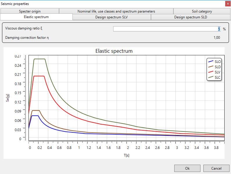
The window displays the elastic spectra corresponding to the Serviceability Limit States and to the Ultimate Limit States. They are defined according to the above mentioned parameters and the formulations provided by Italian NTC.
Moreover, the user can edit:
- the value of the viscous damping ratio ξ (expressed as a percentage) according to the materials, to the structural typology and to the soil category.
The related damping correction factor η modifies the response spectrum in case of ξ different from 5%.
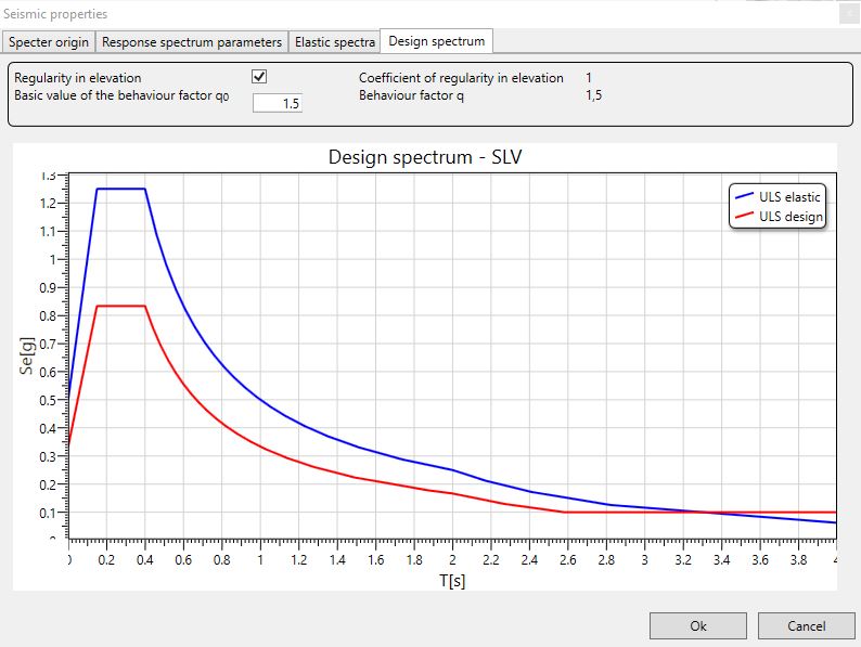
5.2.2.5 Regulation spectra - Design spectrum SLV
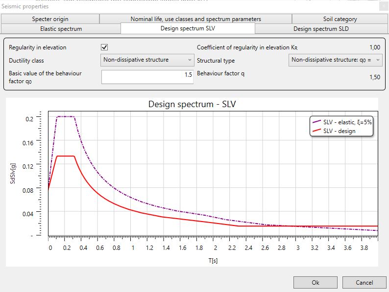
The dialog box displays the design spectrum as a red line. This spectrum is obtained by applying the behaviour factor q that takes into account the inelastic dissipative capacity of the structure together with its overstrength and the increase of its period as a result of plasticisation.
The design spectrum Sd(T) is obtained by reducing the corresponding elastic spectrum according to the formulations 3.2.3.2.1 where η is equal to 1/q.
In the dialog box the user can:
-
define whether the structure is regular in elevation or not;
-
define the ductility class;
-
define the structural type on whose basis the behaviour factor is defined;
-
modify, if necessary, the basic value of the behaviour factor q0 provided by the NTC at point 7.7.3.
The dialog box provides:
-
the coefficient of regularity in elevation KR, which is equal to 1 in case of regularity in elevation and 0,8 otherwise;
-
the behaviour factor calculated from the formulation q = q0· KR.
5.2.2.6 Regulation spectra - Design spectrum SLD and SLO
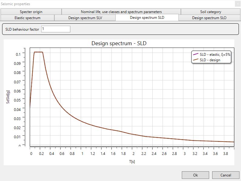
The dialog box displays the design spectrum according to the Damage Limit States and to the Operativity Limit States (only for usage class III or IV structures).
If NTC 2018 is set as reference standard, the user can enter a behaviour factor in order to reduce the Damage Limit State spctrum.
5.3 Snow/Wind Italian Standard

The Snow/Wind command, that is only available when using the Italian NTC standard as reference standard, allows the user to complete the definition of these loads that the software automatically defines according to the site geolocation.
The wind load and the snow one are obtained according to the NTC provisions at point 3.3(Wind loads) and 3.4 (Snow loads).
5.3.1 Snow
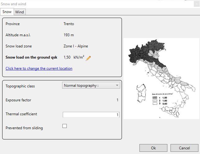
In the dialog box the user can:
-
select from the drop-down menu the site topographic class according to the location of the structure;
-
edit the thermal coefficient Ct;
-
set whether the snow is prevented from sliding or not;
-
edit, if necessary, the site geolocation.
The dialog box provides:
-
the province where the structure is located;
-
the site altitude in meters above sea level;
-
the Snow load zone ;
-
the snow load on the ground qsk (that can be edited if needed);
-
the exposure factor CE;
5.3.2 Wind

In the dialog box the user can:
-
select the site roughness class from the drop-down menu according to the structure location;
-
select the distance from the coast from the drop-down menu in order to define the exposure category;
-
edit the dynamic factor Cd;
-
edit the topography factor Ct.
The dialog box provides:
-
the province where the structure is located;
-
the site altitude in meters above the sea level;
-
the wind load zone;
-
the exposure category of the site;
-
the reference mean (basic) velocity pressure q0 (that can be edited if needed).
5.4 Wind Eurocode

The Wind command, that is only available when using the Eurocodes as reference standard, allows the user to define the wind actions on the structure according to the approach implemented in the internationl version of EN 1991-1-4.
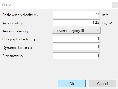
In the dialog box the user can:
-
define the basic wind velocity vb according to the structure location;
-
define the value of the air density;
-
select the terrain category from the drop-down menu according to the structure location;
-
define the value of the orography factor co;
-
define the value of the dynamic factor cd;
-
define the value of the size factor cs.
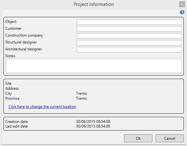
5.5 Project information

The command Project informations allows the user to type, in the dialog box, the informations about the project object, the customer, the construction company, the structural designer and the architectural designer. In the dialog box the user can modify, if necessary, the site geolocation.
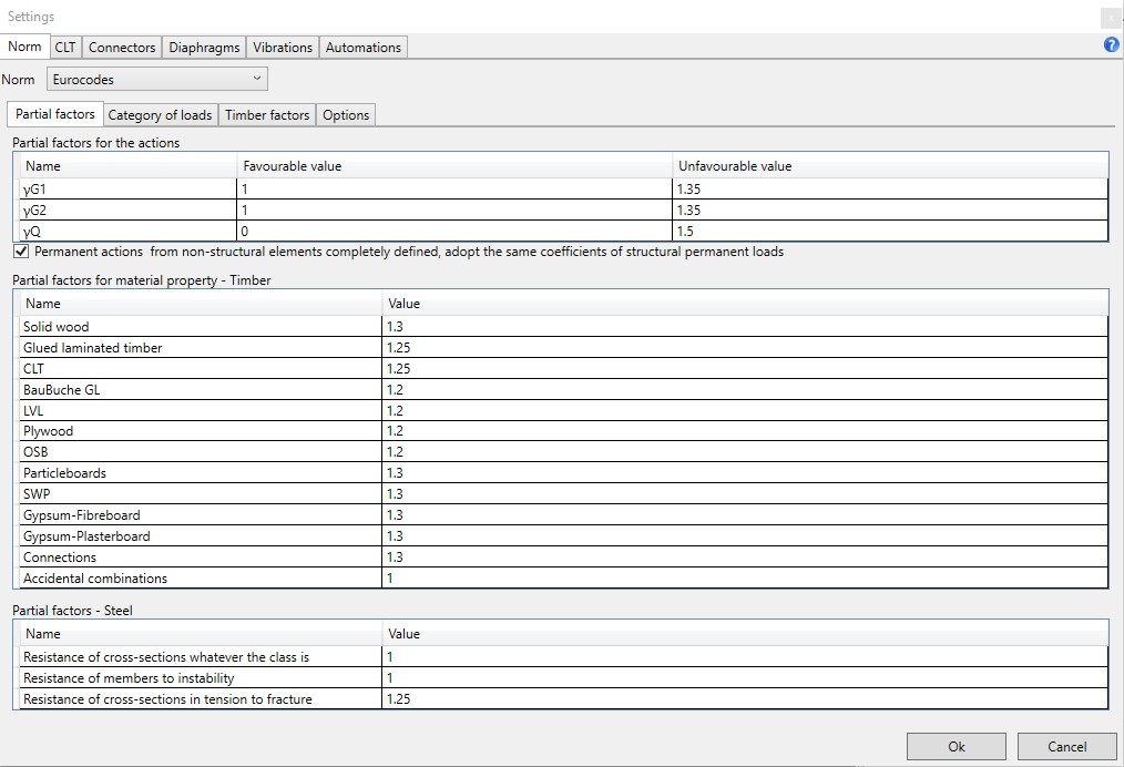
5.6 Settings

5.6.1 Norm
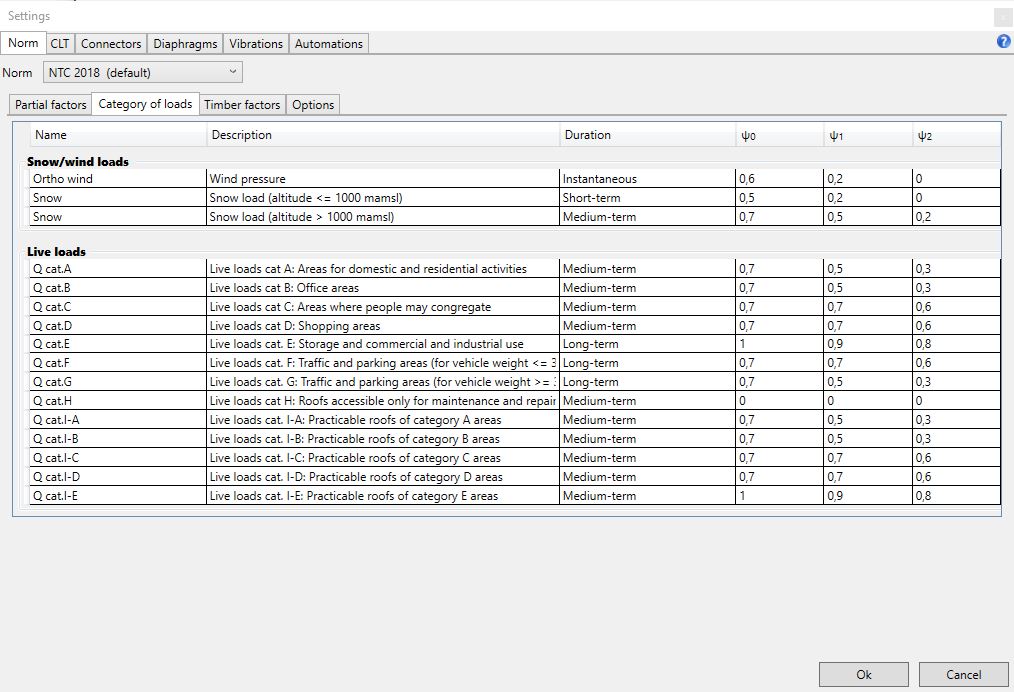
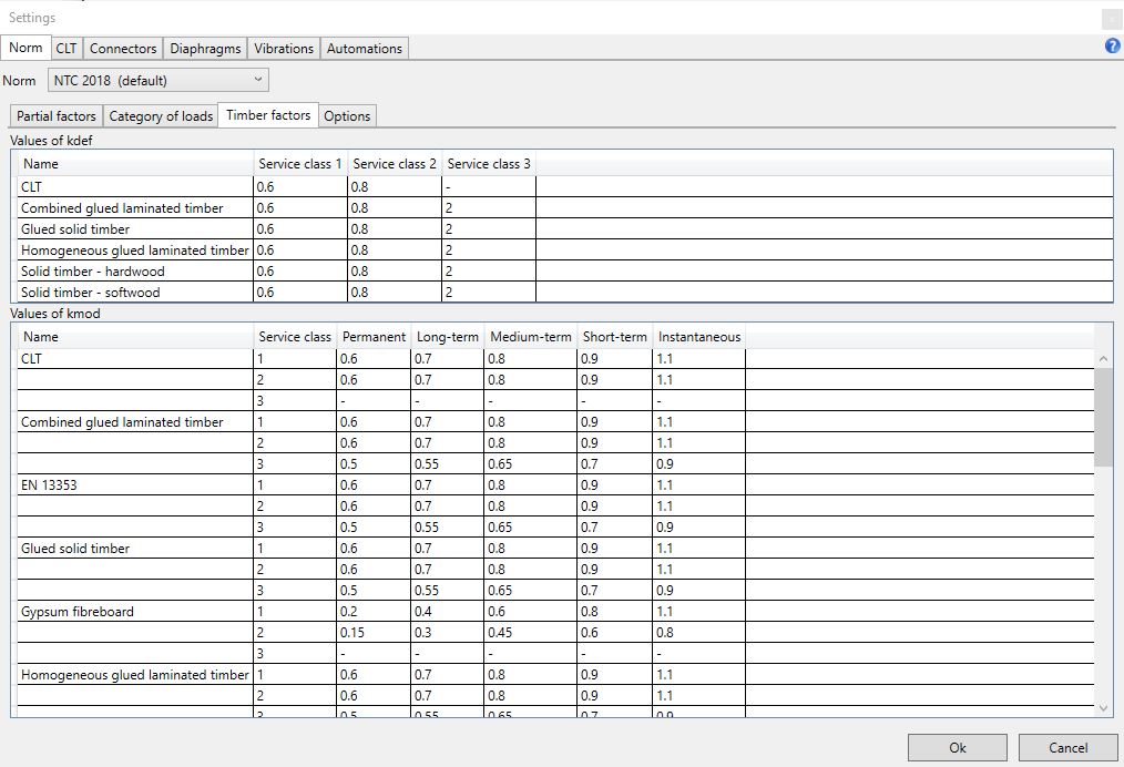
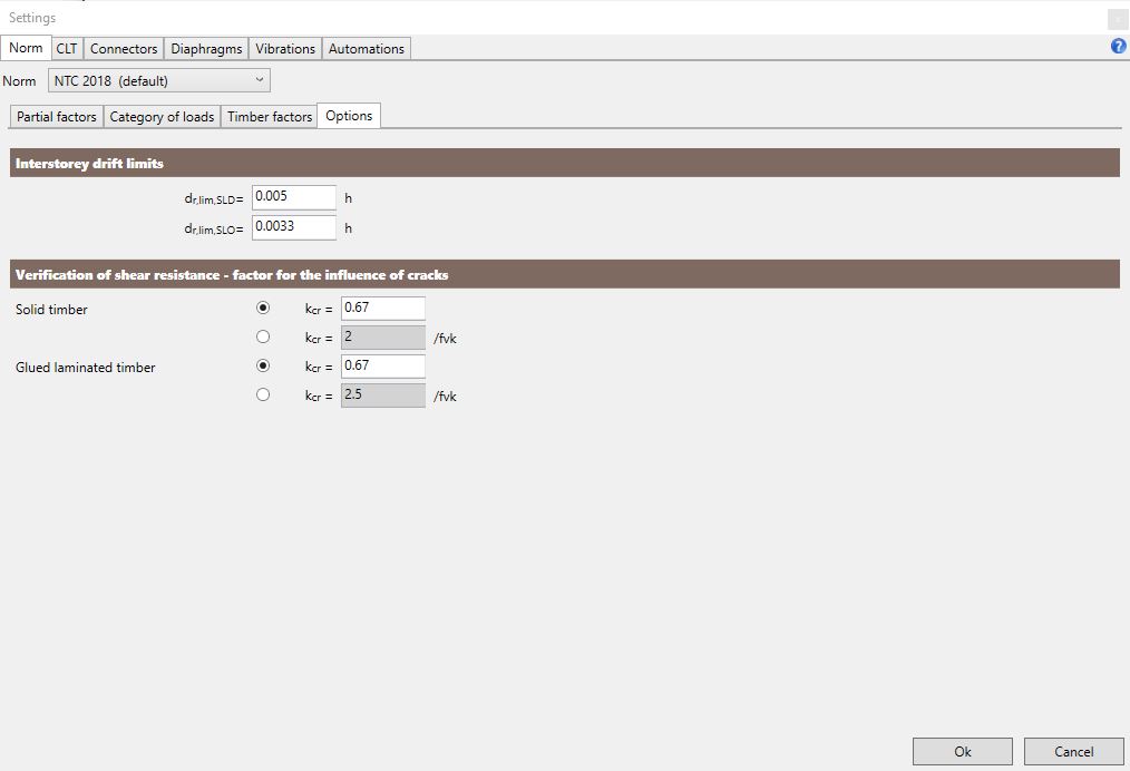
The command provides the access to the table reporting the partial factors for the actions, the partial factors for timber and steel checks, the loads combination factors, the timber factors kdef and kmod, the interstorey drift limits and the factor for the influence of cracks in the shear verification of timber beams.
5.6.2 CLT
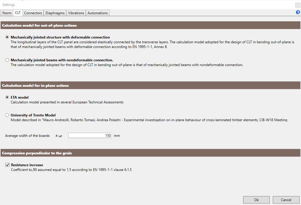
The tab CLT allows the user to choose the calculation model used to verify the CLT elements. With regard to the out of plane loads, the user can choose two methods:
-
model based on the assumption of mechanically jointed structure with deformable connection;
-
model based on the assumption of mechanically jointed beam with non-deformable connection.
With regard to the in-plane actions, the user can choose between:
-
ETA model;
-
Model developed by the University of Trento.
The user can even:
- modify the average width of the boards aref. The parameter is used to calculate the in-plane strength and the assumed shear modulus Geff calculated according to the model proposed in: Verification fo CLT-plates under loads in plane, Bogensperger T., Moosbrugger T., Silly G.
- increase the compression strength perpendicular to the grain assuming kc equal to 1,5.
5.6.3 Connectors
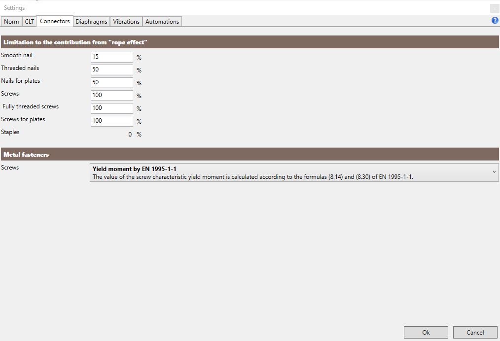
The Connectors tab allows the user to set percentage limitations to the contribution of the rope effect to the shear capacity of dowel-type metal fasteners and to choose the calculation mode for the yield moment of screws.
5.6.4 Diaphragms
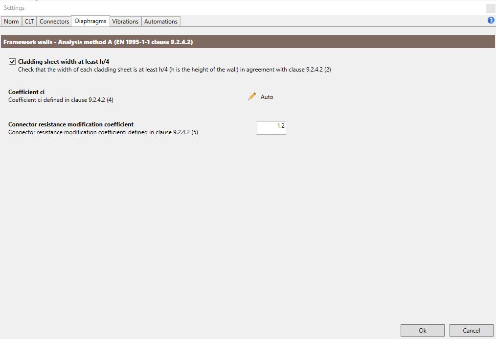
The Diaphragms tab allows the user to specify the following settings required for the calculation of framed walls according to method A provided in section 9.2.4.2 of EN 1995:
-
enable or disable the check on the minimum width of the sheeting boards in a framed wall;
-
edit the value of the ci coefficient that considers the shape of the sheeting panels for the calculation of the framed walls capacity;
-
edit the value of the connector resistance modification coefficient mentioned at point 9.2.4.2(5) of EN 1995.
5.6.5 Vibrations
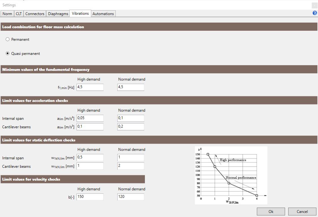
The Vibrations tab allows the user to specify the following settings required for the vibration checks of the floors:
-
the load combination used in the calculation of the floor mass;
-
the minimum values of the fundamental frequency of the floor (with reference to high and normal demand);
-
the limiting values for the acceleration checks on internal and cantilivered spans of floors (with reference to high and normal demand). This kind of check is only available for floors whose fundamenta frequency is between 4.5 and 8 Hz;
-
the limiting values for the static deflection checks on internal and cantilivered spans of floors (with reference to high and normal demand);
-
the limiting values for velocity checks (with reference to high and normal demand). This kind of check is only available for floors whose fundamenta frequency is higher than 8 Hz according to section 7.3.3 of EN 1995.
5.6.6 Automations
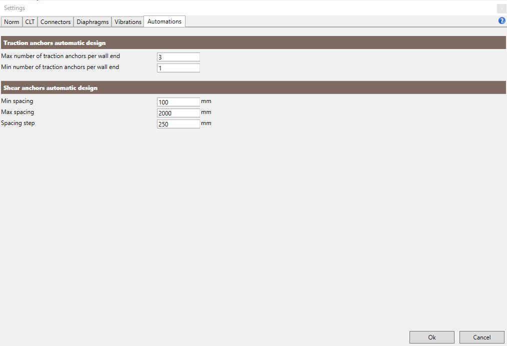
The Automations tab allows the user to specify the following settings required for the auto-design of connections:
-
maximum number of tensile connections at each wall end (between 1 e 6);
-
minimum number of tensile connections at each wall end (between 0 e 5);
-
minimum spacing between shear connections;
-
maximum spacing between shear connections;
-
spacing step considered in the iterative procedure of auto-design of shear connections.