7. Analysis tools
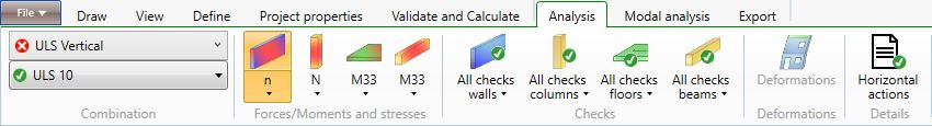
The Analysis menu allows the user to examine the analysis results in terms of forces, moments, stresses and deformations of the structural elements and in terms of resistance, stability, deflection and vibration checks.
7.1 Combination
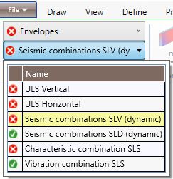
The drop-down menus in the Combination section, allows the user to select a load case or a combination of actions according to which display the stress levels or the checks of the structural elements. A red symbol near a load case/combination in the drop-down menu means that there is at least a not met check according to the selected combination.
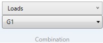
7.1.1 Loads
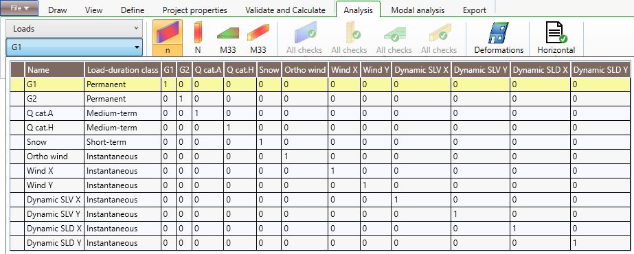
If the user selects Loads in the first drop down menu, in the second one he can select a specific load category according to which he wants to display the stress levels in the structural elements.
7.1.2 Envelopes
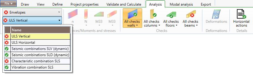
If the user selects Envelopes in the first drop down menu, in the second one he can select the combination category according to which he wants to display the most demanding actions and checks on the structural elements.
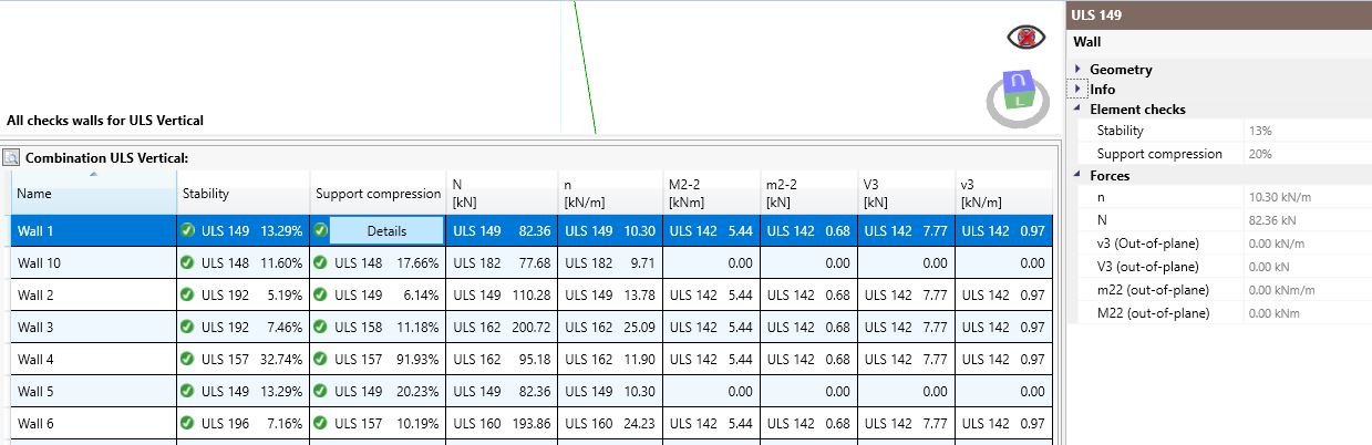
7.1.3 ULS Vertical
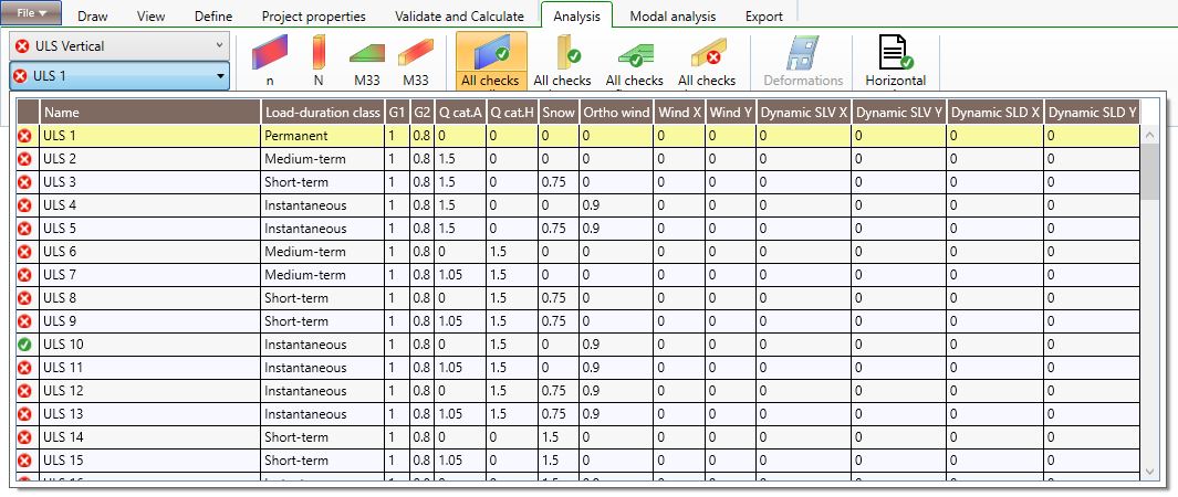
If the user selects ULS Vertical or ULS Horizontal in the first drop down menu, in the second one he can select the specific combination according to which he wants to display the stress levels and the checks of the structural elements at ultimate limit states in static conditions. The combinations are defined according to the selected reference standard.
In the case of timber elements checks, if a load combination includes actions corresponding to different duration classes, the software will consider the kmod factor relevant to the action of the shortest duration. This is why the software automatically considers all the combinations: find out the most demanding one is not elementary.
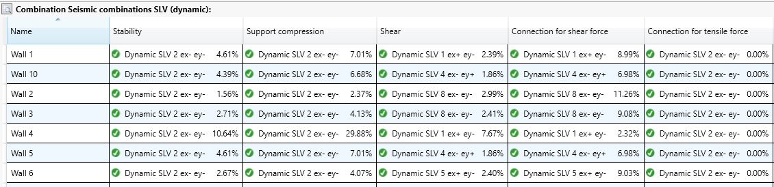
7.1.4 Seismic Combinations
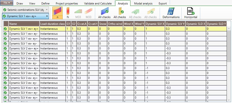
If the user selects Seismic combinations SLV (dynamic or static) or Seismic combinations SLD/SLO (dynamic or static) in the first drop down menu, in the second one he can select one out of 32 combinations according to which he wants to display the stress levels and the checks of the structural elements at ultimate or serviceability limit states in seismic conditions. The 32 combinations take into account the accidental eccentricity of the centre of the masses and the combination of the seismic actions in the two main directions (100% of the value in one direction and 30% in the other direction) according to the selected reference standard.
7.1.5 Characteristic combinations SLS
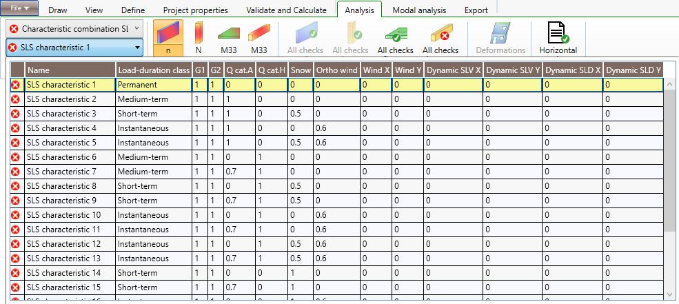
If the user selects Characteristic combination SLS or Vibration combination SLS in the first drop down menu, in the second one he can select the specific combination according to which he wants to display the deflection checks of the structural elements and the vibration checks of the floors at serviceability limit states.
7.2 Forces/Moments and stresses
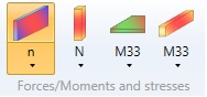
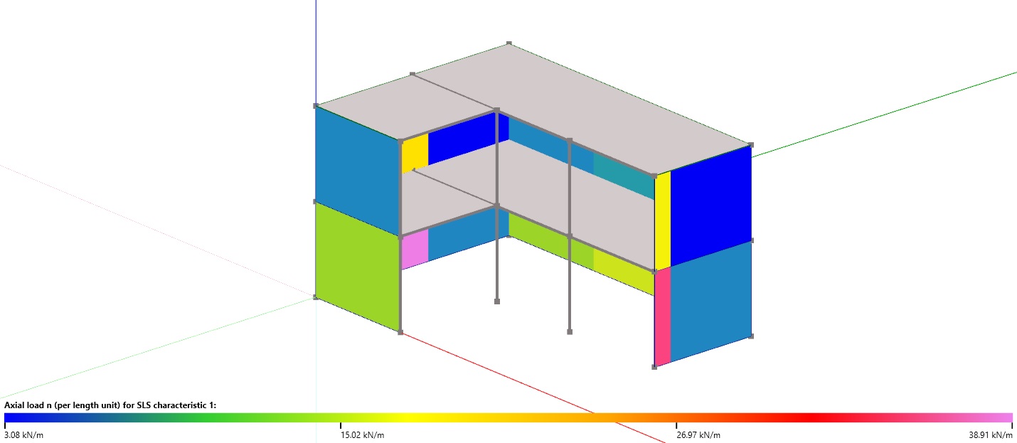
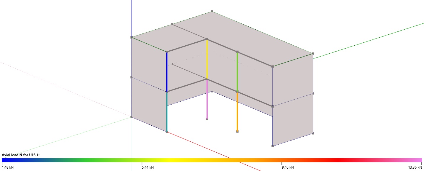
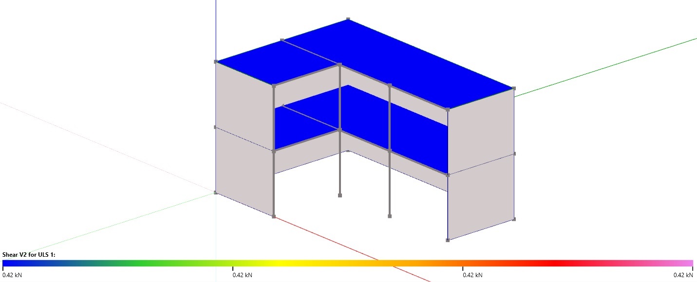
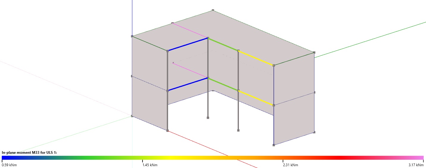
The menu allows the user to display (with different colour shades) the forces/stresses level on the structural elements arising from the selected load/load combinations. A colour spectrum ranging from the minimum to the maximum level of forces/stresses of the selected element type is displayed on the bottom side of the screen. The table below the colour spectrum provides in detail the values of the forces, of the moments and of the stresses of the elements belonging to the selected type.
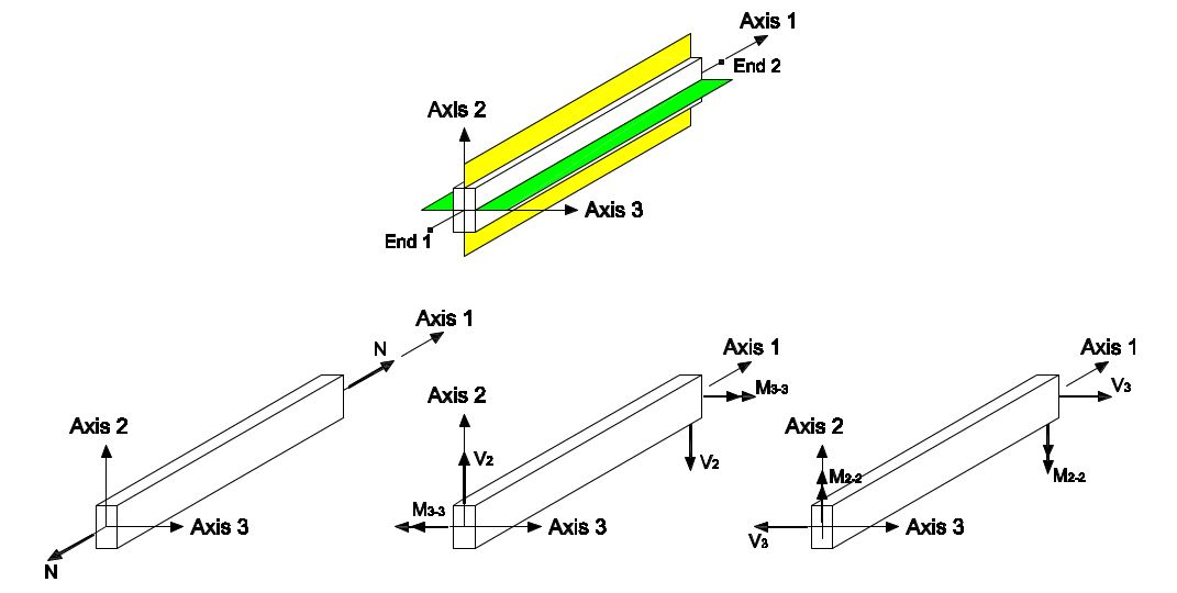
Each element (column, beam, wall, floor) of the structural model has its own coordinate system that is used to define the stresses and the forces on the element. The coordinate systems used to define the Beam elements are schematically shown in the following figures.
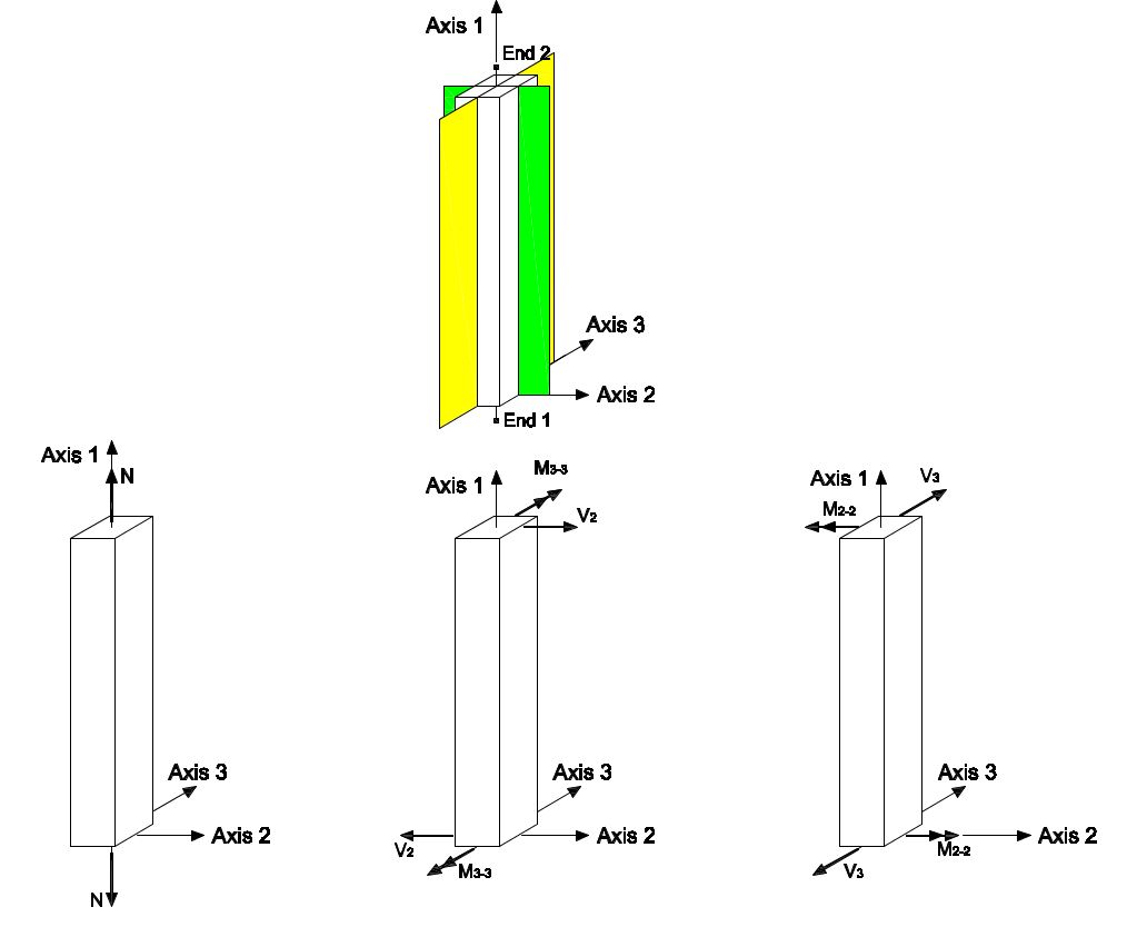
The coordinate system used to define the Column elements is displayed in the following figure:
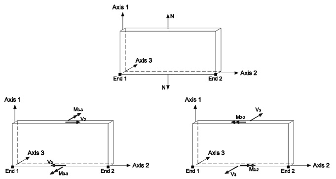
The coordinate system used to define the Wall elements is displayed in the following figure:
7.2.1 Wall

The user can select, in the drop-down menu, the structural response he wants to display:
-
n: axial stress per unit length;
-
m22: bending moment about the local axis 2 (out of plane moment) per unit length;
-
v3: shear along local axis 3 per unit length;
-
m33: bending moment about the local axis 3 (in plane moment) per unit length ;
-
v2: shear along local axis 2 per unit length;
-
Va: force on the shear connections;
-
Ta: force on the tensile connections.
In the drop-down menu the user can only select the element responses relevant for the selected action/combination of actions.
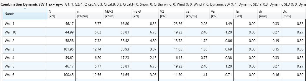
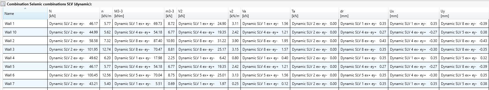
The table below the model display window provides the maximum forces/stresses and moments:
-
N: total axial force (integration of n along the wall length);
-
M2-2: bending moment about local axis 2 that is the integral of m22 along the wall length;
-
V3: total shear force (integration of v3 along the wall length);
-
M3-3: bending moment about local axis 3 that is the integral of m33 along the wall length;
-
V2: total shear force (integration of v2 along the wall length);
-
Va: force on the shear connections;
-
Ta: force on the tensile connections;
-
n: axial stress per unit length;
-
m22: bending moment about the local axis 2 (out of plane moment) per unit length;
-
v3: shear along local axis 3 per unit length;
-
m33: bending moment about the local axis 3 (in plane moment) per unit length ;
-
v2: shear along local axis 2 per unit length;
-
dr: inter-storey drift;
-
Ux: absolute displacement in X direction;
-
Uy: absolute displacement in Y direction.
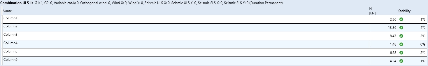
7.2.2 Column

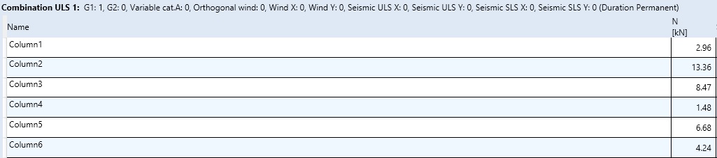
In the drop-down menu the user can select the axial forces.
The table below the model display window provides the axial force values of all the column elements:
7.2.3 Floor

The user can select, in the drop-down menu, the structural response he wants to display:
-
M33: bending moment about the local axes 3 (bending moment in plane 1-2);
-
V22: shear force along local axes 2(Shear 2);
-
Winst: maximum instantaneous deflection;
-
Wfin: maximum final deflection;
-
W1kN: maximum deflection under a 1 kN point load;
-
f1: fundamental frequency of the floor;
-
v: velocity response (vibration check);
-
a: acceleration response (vibration check);
In the drop-down menu the user can only select the element responses relevant for the selected action/combination of actions.
The user can select, in the drop-down menu, the forces/moments or the deformation corresponding to the selected Combination.
The table, below the model display window, provides the maximum values of the forces and deformations.

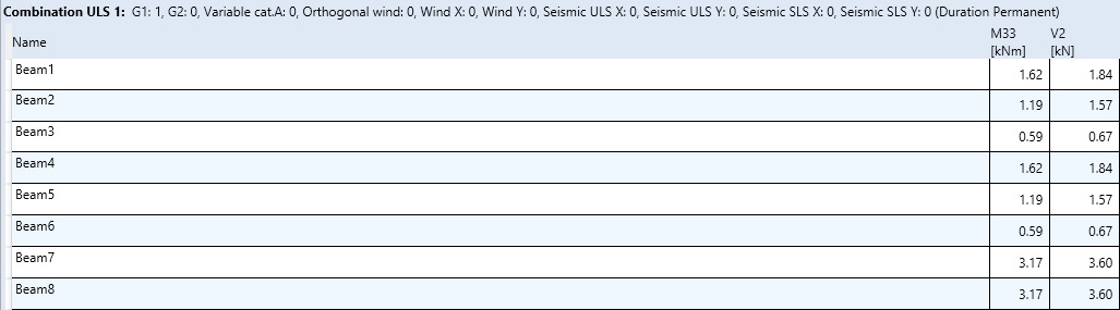
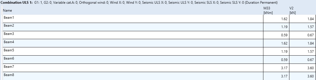
7.2.4 Beam

The user can select, in the drop-down menu, the structural response he wants to display:
-
M33: bending moment about the local axes 3 (bending moment in plane 1-2);
-
V22: shear force along local axes 2(Shear 2);
-
Winst: maximum instantaneous deflection;
-
Wfin: maximum final deflection;
-
W2: maximum deflection due the live loads.
In the drop-down menu the user can only select the element responses relevant for the selected action/combination of actions.
The table below the model display window provides the maximum values of the forces and deformations.
7.3 Checks
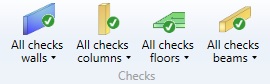
The table below the model display window provides the elements checks as a percentage of the maximum value of their strength according to the considered failure modes.
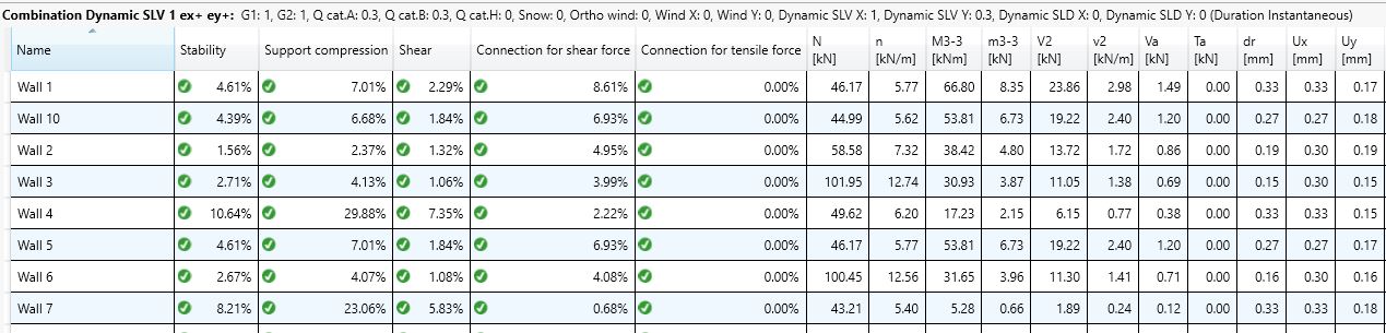
7.3.1 Wall

The user can select one of the following checks:
-
Wall stability;
-
Compression wall support;
-
Shear;
-
Shear on connections;
-
Tension on connections;
-
Displacement.
In the drop-down menu the user can only select the element checks relevant for the selected combination of actions.
The table below the model display window provides the elements checks in percentage.
7.3.2 Column

The user can choose to display the stability checks.
7.3.3 Floor

The user can select one of the following checks:
-
Shear;
-
Bending;
-
W: maximum deflection;
-
Vibrations.
In the drop-down menu the user can only select the element checks relevant for the selected combination of actions.
The table below the model display window provides the elements checks in percentage.

7.3.4 Beam

The user can select one of the following checks:
-
Shear;
-
Bending;
-
W: maximum deflection.
In the drop-down menu the user can only select the element checks relevant for the selected combination of actions.
The table below the model display window provides the elements checks in percentage.
7.4 Deformations

The Deformations command allows the user to display the model deformations due to the horizontal loads. This command is available only when wind or seismic loads are included in the selected combination of actions.
Note: the user can display the deformations due to the vertical loads, selecting the element (floor or beam) he wants to examine and the desired combination and then clicking the Details button.
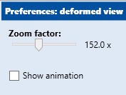
It is also possible to increase and to reduce the zoom factor with the slider shown in the previous figure. To deeply understand the structural deformation, the user can also run the model animation.
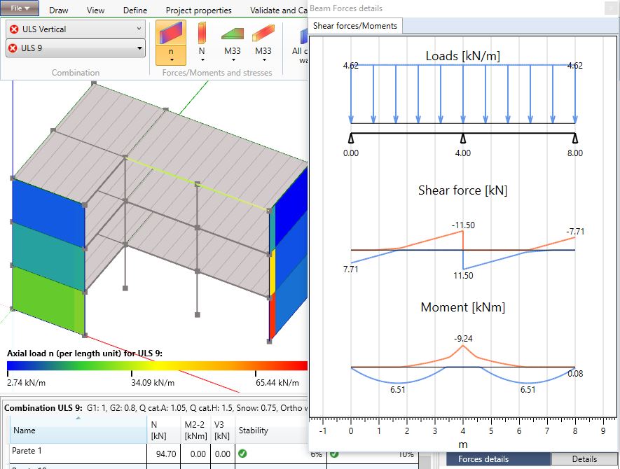
Note: once a beam or a floor element is selected, the user can display the deformations due to the vertical loads by clicking the Details button.
7.5 Details

7.5.1 Horizontal actions
The command Horizontal actions provides the access to the summary tables that report the details of the horizontal actions due to wind and seismic loads and the most important parameters used to calculate them.
7.5.1.1 Wind
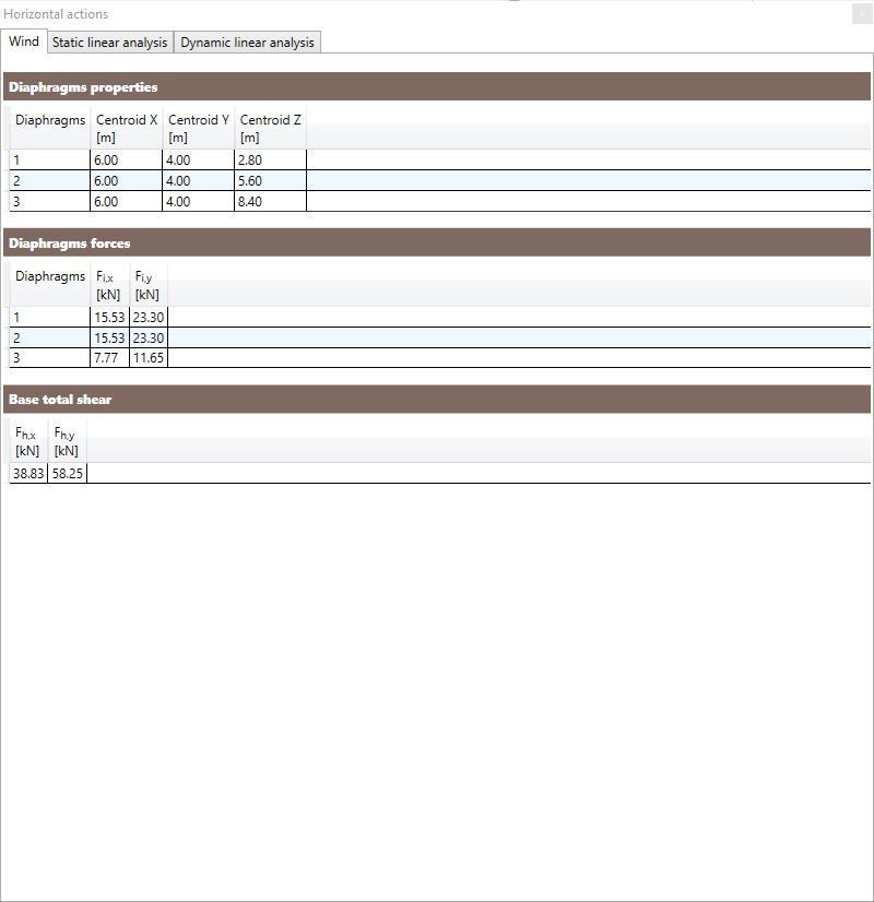
The tables provides, for each diaphragms:
-
Centroid X: X coordinate of the centroid of the surface perpendicular to the Y direction hit by the wind action;
-
Centroid Y: Y coordinate of the centroid of the surface perpendicular to the X direction hit by the wind action;
-
Centroid Z: Z coordinate of the centroid of the surface hit by the wind action;
-
Fi,x: force acting along X direction on the i-th diaphragm;
-
Fi,y: force acting along Y direction on the i-th diaphragm;
-
Fh,x: total force, at the base of the structure, acting along X direction;
-
Fh,y: total force, at the base of the structure, acting along Y direction.
7.5.1.2 Static linear analysis
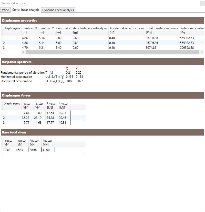
The Diaphragms properties table provides the following data:
-
Centroid X: X coordinate of the diaphragm centroid;
-
Centroid Y: Y coordinate of the diaphragm centroid;
-
Centroid Z: Z coordinate of the diaphragm centroid;
-
ex, ey: accidental eccentricity in X direction and in Y direction according to the selected reference standard;
-
total translational mass: sum of all the loads and masses acting on each diaphragm according to the seismic combination;
-
the rotational inertia of all the loads and masses acting on each diaphragm according to the seismic combination.
The table Response spectrum provides the following data:
-
the fundamental period T1 in X and Y direction according to the formulations porposed by the reference standard;
-
the ULS response spectrum value corresponding to the fundamental period T1 in X and Y direction;
-
the SLD/SLO response spectrum value corresponding to the fundamental period T1 in X and Y direction.
The other two tables provide:
-
Fi,x: the force acting along X direction on the i-th diaphragm (in case of SLV and SLD/SLO);
-
Fi,y: the force acting along Y direction on the i-th diaphragm (in case of SLV and SLD/SLO);
-
Fh,x: the total force, at the base, acting along X direction (in case of SLV and SLD/SLO);
-
Fh,y: the total force, at the base, acting along Y direction (in case of SLV and SLD/SLO).
7.5.1.2 Dynamic linear analysis
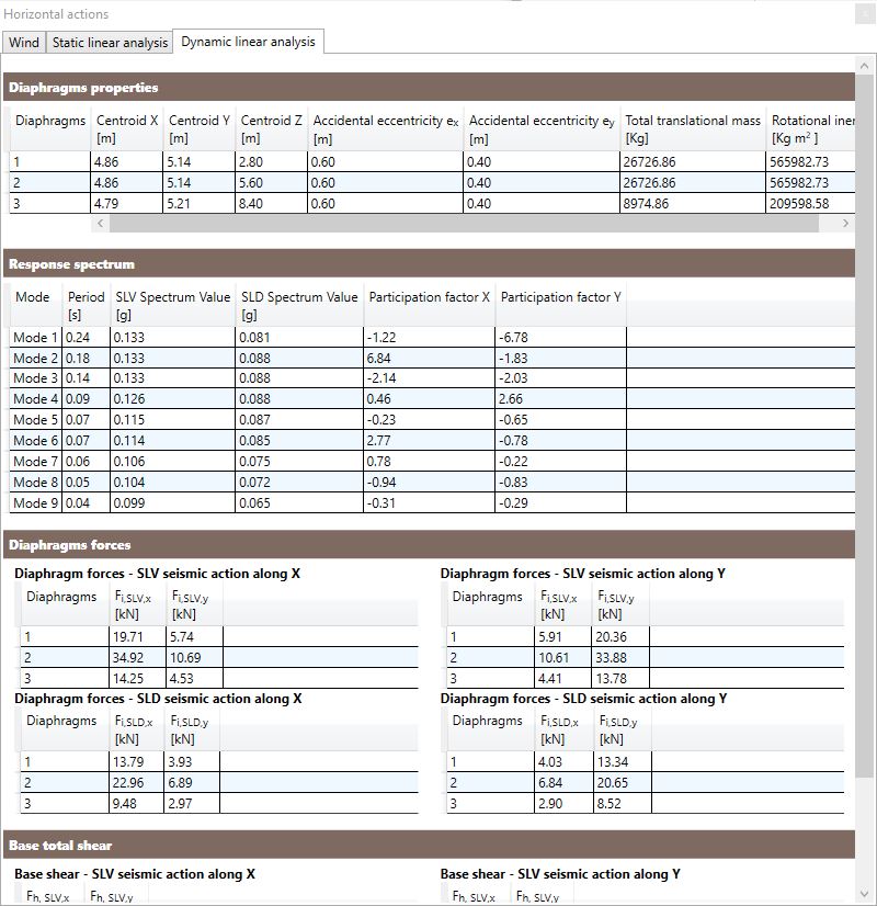
The Diaphragms properties table provides the following data:
-
Centroid X: X coordinate of the diaphragm centroid;
-
Centroid Y: Y coordinate of the diaphragm centroid;
-
Centroid Z: Z coordinate of the diaphragm centroid;
-
ex, ey: accidental eccentricity in X direction and in Y direction according to the selected reference standard;
-
total translational mass: sum of all the loads and masses acting on each diaphragm according to the seismic combination;
-
the rotational inertia of all the loads and masses acting on each diaphragm according to the seismic combination.
The table Response spectrum provides the following data:
-
the mode number and the corresponding period Ti;
-
the SLV and the SLD/SLO response spectrum value corresponding to each period Ti;
-
the partecipation factor along X and Y.
The Diaphgrams forces table provides:
-
Fi,x: the force acting along X direction on the i-th diaphragm (in case of SLV and SLD/SLO and for a seismic action along X and along Y);
-
Fi,y: the force acting along Y direction on the i-th diaphragm (in case of SLV and SLD/SLO and for a seismic action along X and along Y);
The Base total shear table provides:
-
Fh,x: the total force, at the base, acting along X direction (in case of SLV and SLD/SLO and for a seismic action along X and along Y);
-
Fh,y: the total force, at the base, acting along Y direction (in case of SLV and SLD/SLO and for a seismic action along X and along Y).
7.6 Checks, actions and deformations envelopes
The Envelopes feature and all its available options is fundamental in order to effectively manage the analysis results.
Once the user selects Envelopes in the first drop down menu of the Combinations section and the combination category according to which he wants to display the most demanding actions and checks in the second one, the following features are available.
7.6.1 Checks envelopes
The checks envelopes are reported on the left side of the table below the window displaying the model.
The highest percentage value of each check on the structural elements is provided according to the most demanding combination of actions. Consequently, the name of the most demanding combination for each check is also provided.
It should be noted that the combination of actions that maximizes a check on a structural element can differ from the combination that maximize the relevant action. This is due to the influence of the duration coefficient kmod that, if relevant, modifies the design capacity of the material.
7.6.2 Actions and deformations envelopes
The actions and deformations envelopes are reported on the right side of the table below the window displaying the model.
The highest action and deformation values on the structural elements are provided according to the most demanding combination of actions. Consequently, the name of the most demanding combination for each action or deformation type is also provided.
It should be noted that the combination of actions that maximizes an action on a structural element can differ from the combination that maximize the relevant check. This is due to the influence of the duration coefficient kmod that, if relevant, modifies the design capacity of the material.
7.6.3 Link to the relevant combination of actions
When, while displaying the envelopes, the user selects a single row of the table below the window displaying the model, the details of the selected element according to the combination of actions that maximizes each check/action/deformation are made available.
When the mouse pointer is over a cell of the selected row in the table, a button activates that synchronize the Property inspector with the most demanding combination of actions for the check/action/deformation considered in the selected cell.
Note: the link is only available when a single element is selected.
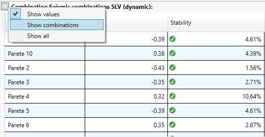
7.6.4 Displaying settings
While visualizing the envelopes, the user can choose whether to display or not the name of the combination of actions that maximizes each check/action/deformation in the table below the window displaying the model.
7.7 Modal analysis
The Modal Analysis command allows the user to display the vibration modes of the structure. For each mode, the software provides the period, the frequency, the participating masses and the modal deformations.
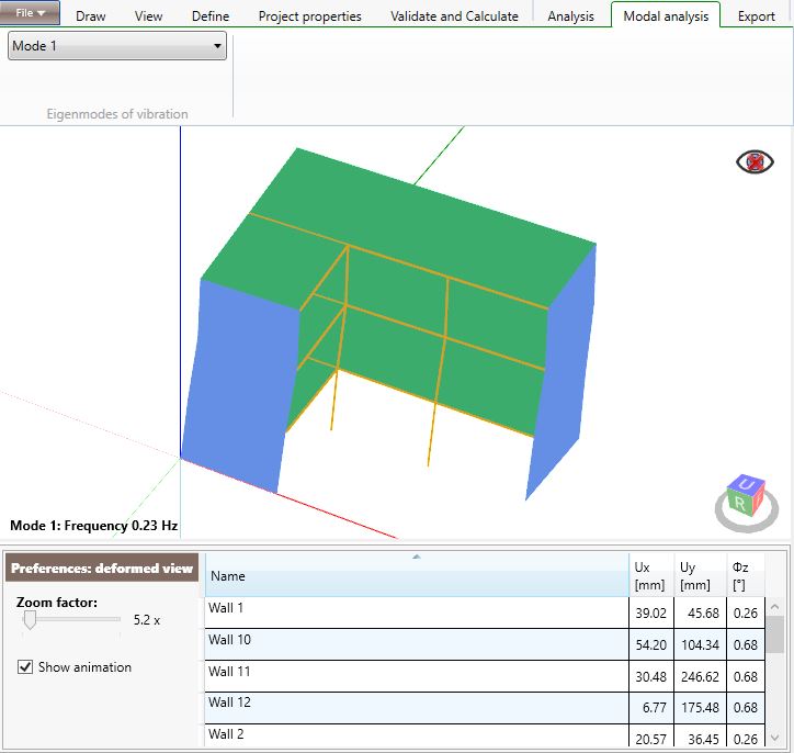
The user can set the zoom factor and activate the mode animation.
7.8 Export

By using the commands in the Export tab you can:
-
Print and view or save the calculation report in Micorsoft Word format;
-
Export the drawings in DXF format of the plants, elevations and sections of the analyzed structure;
-
Export the model in IFC format;
-
Export the base reactions of the structure in order to design the foundation elements.
7.8.1 Print
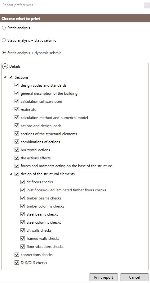
If the user selects the Print report command, he can select which sections to print.
7.8.2 Export reactions in foundation
The command "Export reactions in foundation" allows the user to export the geometry of the walls at the base of the structure and the respective base reactions deriving from the analysis. The output is in numerical format (a text file .csv) and in graphic format (.dxf). The reactions are exported in the form of concentrated forces and moments in a determined number of nodes, depending on the choices made by the user. These nodes are exported for all the walls that have the base at z = 0 or that rest on a foundation element.
Specifically, the output consists of three files
-
geometry.csv: is a text file containing the position of the nodes in which the exported joint reactions are assumed to be concentrated. In the first column of the file there is the node ID, that is the univocal identification number of the node: note that this number does not correspond to the number of the wall to which the node belongs. The following columns show the Cartesian coordinates X, Y, Z of the node with respect to the origin of the axes;
-
geometry.dxf: is a drawing file containing the position of the nodes in which the exported joint reactions are assumed to be concentrated;
-
actions.csv: is a text file containing the following data in the form of values separated by commas: - the ID of the nodes, - the respective coordinates that define their position in the space, - the name of the load combination or load case and - the base reactions in each node in the form of three force components (one for each direction: Fx, Fy and Fz) and three components of bending moment (one for each direction: Mxx, Myy and Mzz).
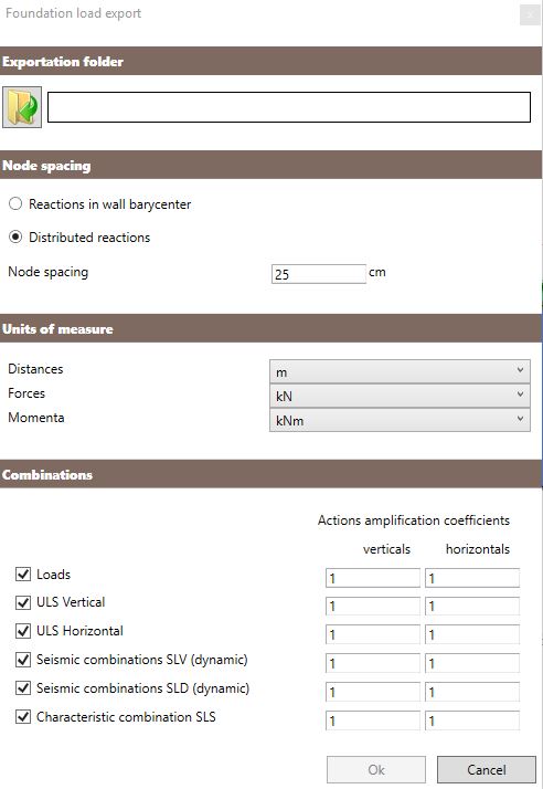
The user can set some exportation options:
-
The folder where export the files with the base reactions. The OK button is disabled until a destination folder is not selected;
-
The spacing of the nodes. You can export the base reactions in a single node for each wall (Reactions in the wall barycentre) or export the reactions in several nodes distributed along each wall (Reactions distributed along the wall). In the first case, the node will be placed in the center of the lower side of each wall, while in the second case the software will create and export multiple nodes positioned with constant spacing (chosen by the user) along the bottom edge of each wall.
This option also influences the way in which the bending moments are exported: in the case of a single node for each wall, the software will export the moment as a pair of forces applied to the node itself, in the case of nodes distributed at the base of the walls the software will export the moment as a set of vertical forces applied to the aforementioned nodes. In this last case the values of the variables Mxx, Myy and Mzz will always be null. -
The units of measurement related to lengths, forces and moments;
-
The load combinations to export. The user can decide to export the base reactions associated with some or all load combinations generated by the software simply by checking their checkboxes. It is also possible to export the reactions associated to the individual load cases.
-
Actions amplification coefficient. The reactions at the base of the structure can be exported as they result from the analysis or modified by means of the amplification coefficients. It is possible to set these coefficients with different values for the different load combinations; it is also possible to set different values of the coefficients for vertical loads (such as the weight of the structural elements or the live load) and horizontal ones (such as wind and earthquake).
7.8.2.1 Sign conventions
The forces and moments applied in a node when exported are resolved into components parallel to the main axes (x, y and z).
The sign conventions adopted for the export of the base reactions are as follows: